Forming mould of high-toughness magnesium alloy thin-web high-reinforcement forging with flow-dividing bin
A forming die and magnesium alloy technology, which is applied in the field of forming dies for high-strength and tough magnesium alloy thin-walled and high-reinforced forgings, and in the field of forming dies for magnesium alloy thin-walled and high-reinforced forgings. It can solve the problem of flashing and deformation resistance on the surface of forgings Large, dissatisfied and other problems, to achieve the effect of improving surface shape accuracy, improving magnesium alloy structure, and reducing mold pressure
- Summary
- Abstract
- Description
- Claims
- Application Information
AI Technical Summary
Problems solved by technology
Method used
Image
Examples
specific Embodiment approach 1
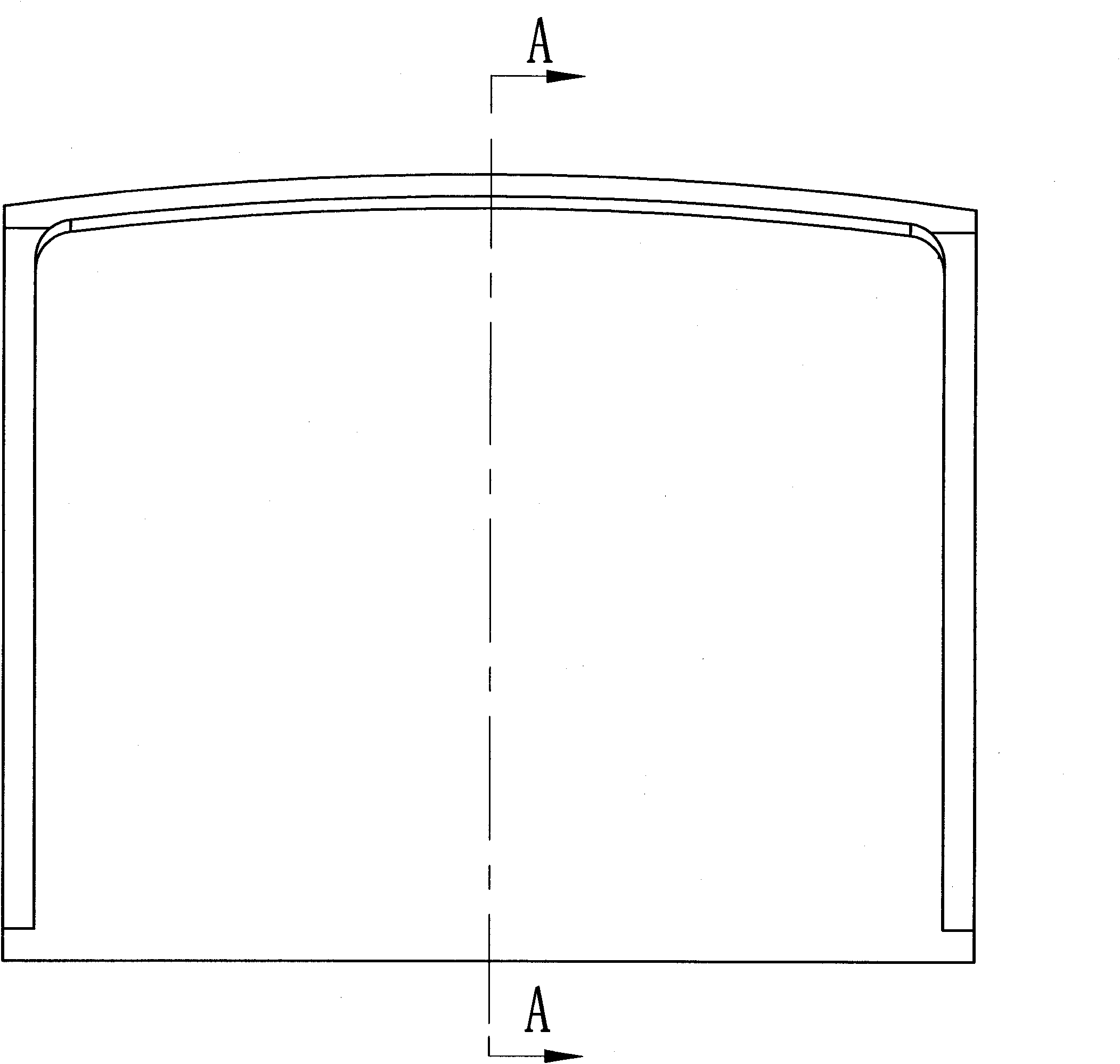
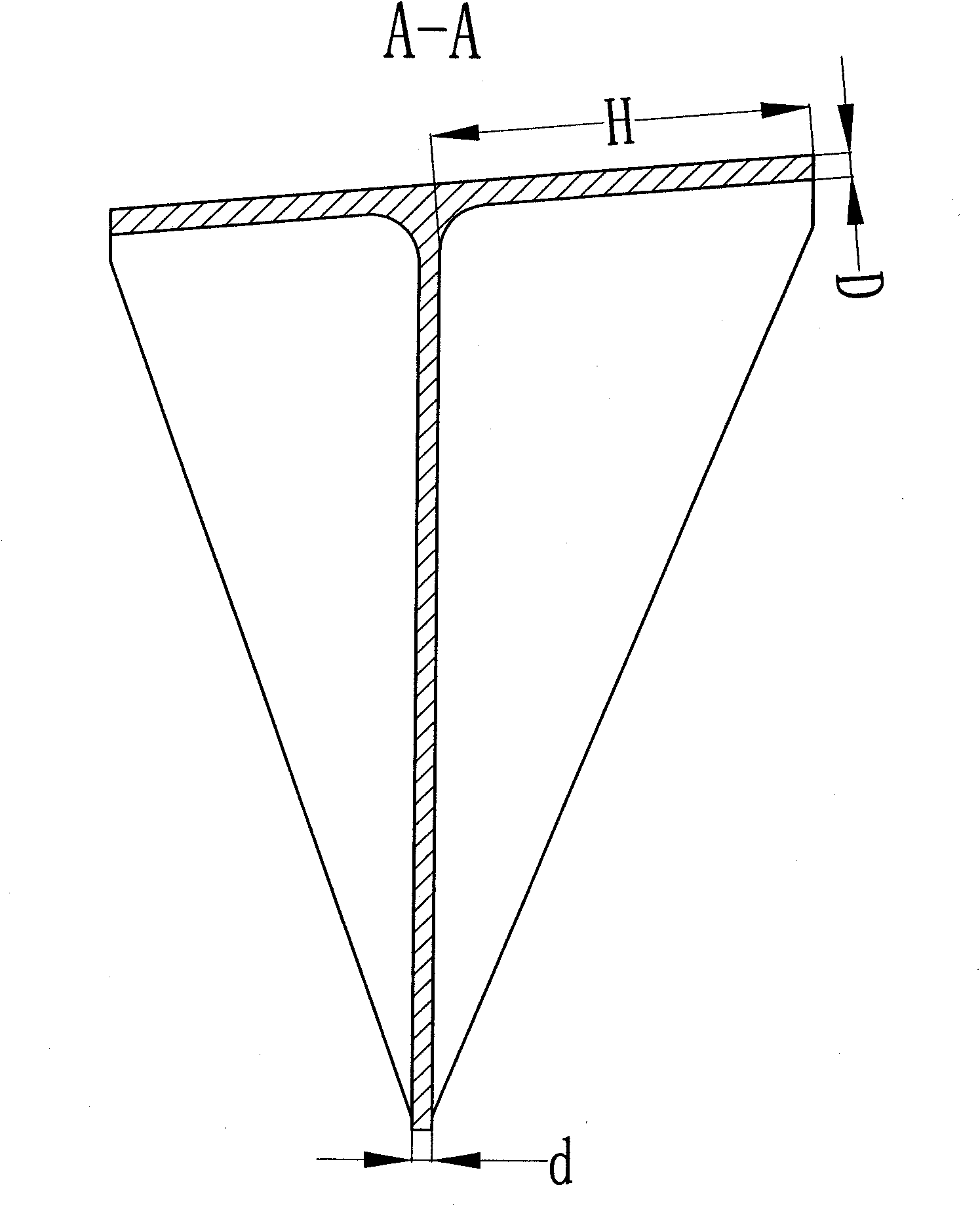
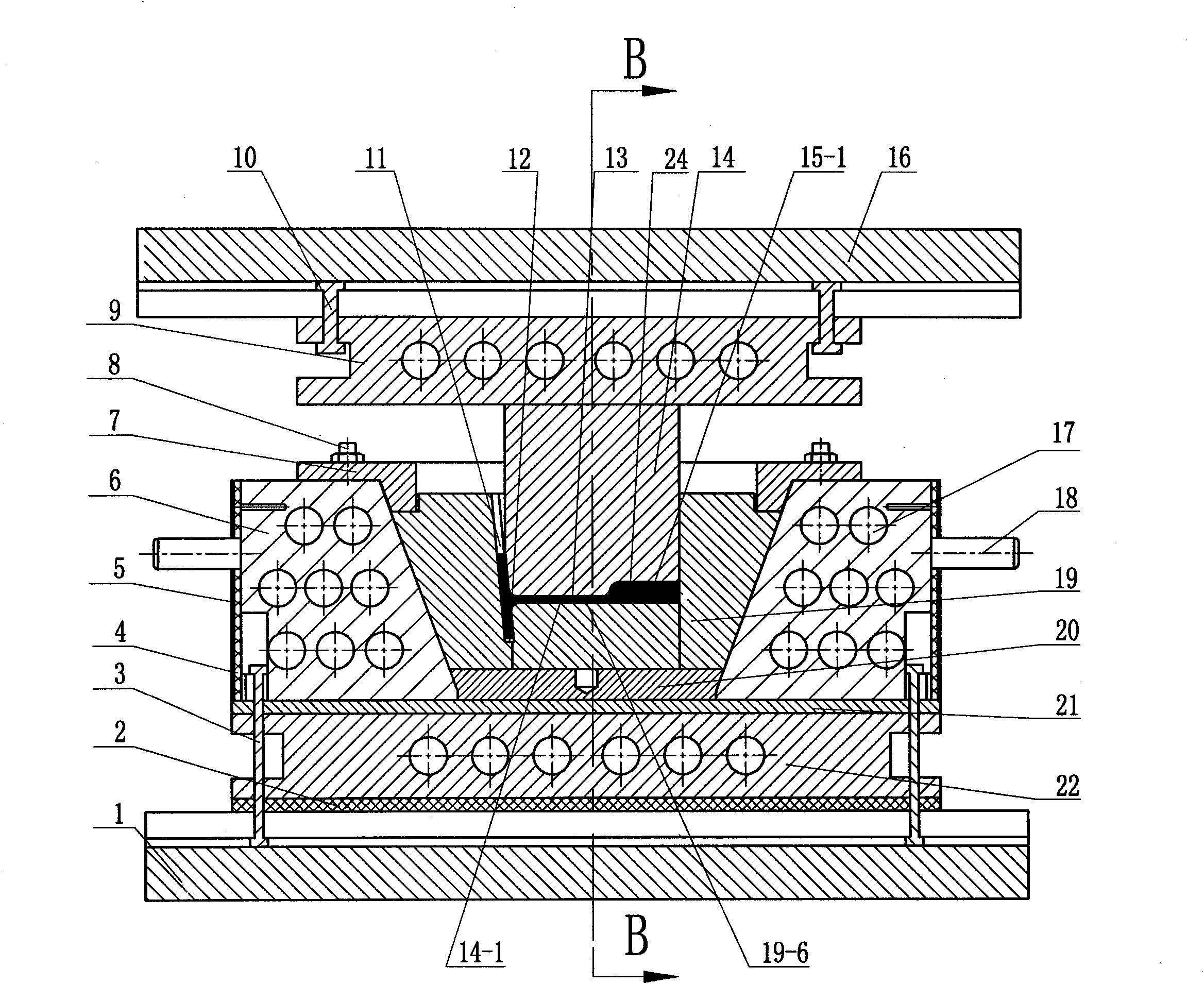
[0008] Specific implementation mode one: as Figure 1-9 As shown, the forming die of the high-strength and tough magnesium alloy thin-walled high-reinforced forging with a shunt chamber described in this embodiment includes a punch 14 and a split die 19, and the split die 19 consists of a first split die 19-1, the second split 19-2, the third split 19-3, the fourth split 19-4 and the die bottom 19-5 are composed of five parts, and the five parts together form a truncated cone shape. One split 19-1 and the third split 19-3 are arranged oppositely, and the second split 19-2 is arranged opposite to the fourth split 19-4. When the punch 14 and the split die 19 were closed, the convex The mold 14 is tightly inserted in the cavity of the split die 19 and completely coincides with the cavity of the split die 19; there is a pressure relief discharge port 11 on the upper part of the inner side wall of the first split die 19-1 , the split line of the split die 19 just coincides with th...
specific Embodiment approach 2
[0011] Specific implementation mode two: as image 3 , 4 , 7 and 8, the forming die described in this embodiment also includes a punch web shunt bin 15-1, on the profile surface 14-1 of the punch 14 corresponding to the non-connecting end of the web, there is a The punch web distribution chamber 15-1, the punch web distribution chamber 15-1 communicates with the web cavity 24-3; the height H3 of the punch web distribution chamber 15-1 is the height of the actually formed forging 1 to 2 times the thickness of the web. The web distribution chamber is set on the profile 14-1 of the punch 14, the web of the formed forging is fully formed, and it is easy to process the web distribution chamber on the profile 14-1 of the punch 14, but the web of the formed forging needs to be for processing. Other components and connections are the same as those in the first embodiment.
specific Embodiment approach 3
[0012] Specific implementation mode three: as Figure 5 and 6 As shown, the forming mold in this embodiment also includes a die web splitter bin 15-2, and the die web splitter bin 15-2 is arranged in the third split lobe corresponding to the web cavity 24-3 On the inner side wall of 19-3, the die web distribution chamber 15-2 communicates with the web cavity 24-3, and the bottom end surface of the web cavity 24-3 communicates with the die web distribution chamber 15-2 The bottom end surfaces are located on the same horizontal plane, and the length of the die web distribution chamber 15-2 is 1 / 6 of the length L of the web of the actually formed forging. The difference between this embodiment and the second embodiment is that the setting positions of the web shunting bins are different. For the web that requires no further processing after forming, the web shunting bin (die web shunting bin 15-2) can be set on the split die. At this time, the die structure is more complicated,...
PUM
| Property | Measurement | Unit |
|---|---|---|
| Thickness | aaaaa | aaaaa |
| Thickness | aaaaa | aaaaa |
Abstract
Description
Claims
Application Information
 - R&D
- Intellectual Property
- Life Sciences
- Materials
- Tech Scout
- Unparalleled Data Quality
- Higher Quality Content
- 60% Fewer Hallucinations
Browse by: Latest US Patents, China's latest patents, Technical Efficacy Thesaurus, Application Domain, Technology Topic, Popular Technical Reports.
© 2025 PatSnap. All rights reserved.Legal|Privacy policy|Modern Slavery Act Transparency Statement|Sitemap|About US| Contact US: help@patsnap.com


