Signal execution unit of computer interlock system and working method thereof

A computer interlocking and execution unit technology, applied in visual signals, railway signals, railway signals and safety, etc., can solve the problems of system state monitoring, long time for output prohibition signal, affecting the service life of switches, etc., to achieve electrical The effect of isolation, fast execution, and improved reliability

Active Publication Date: 2010-12-15
上海亨钧科技股份有限公司
View PDF9 Cites 17 Cited by
  • Summary
  • Abstract
  • Description
  • Claims
  • Application Information

AI Technical Summary

Problems solved by technology

[0005] First of all, the above-mentioned fail-safe unit is composed of a dynamic circuit, and its function is to convert the pulse output by the CPU processing unit A and B into a stable voltage for controlling the switch in the normally closed state. CPU processing units A and B, if the CPU processing unit A and/or B break down, such as the program is out of control, then this kind of control device will not be able to complete the fail-oriented safety, which is a fatal problem for the railway system; in addition, the CPU processing The unit needs to perform error avoidance and fault tolerance processing on various command signals and detection signals according to the preset algorithm, and then output the pulse signal acting on the fail-safe unit according to the analysis results on the software. The response time of this process is 3 to 5 clocks The defect of this processing method is that it increases the probability of fault-oriented safety failure, and the delay time of fault judgment through software is longer than that of direct hardware logic operation (the response time of hardware is different even if different devices are different. at the nanosecond level), therefore, safety guidance cannot be performed in time, which is a very serious problem for railway control systems;
[0006] Secondly, the switch that is in the normally closed state is connected to t...

Method used


Image

  • Signal execution unit of computer interlock system and working method thereof
  • Signal execution unit of computer interlock system and working method thereof
  • Signal execution unit of computer interlock system and working method thereof

Examples


Embodiment Construction

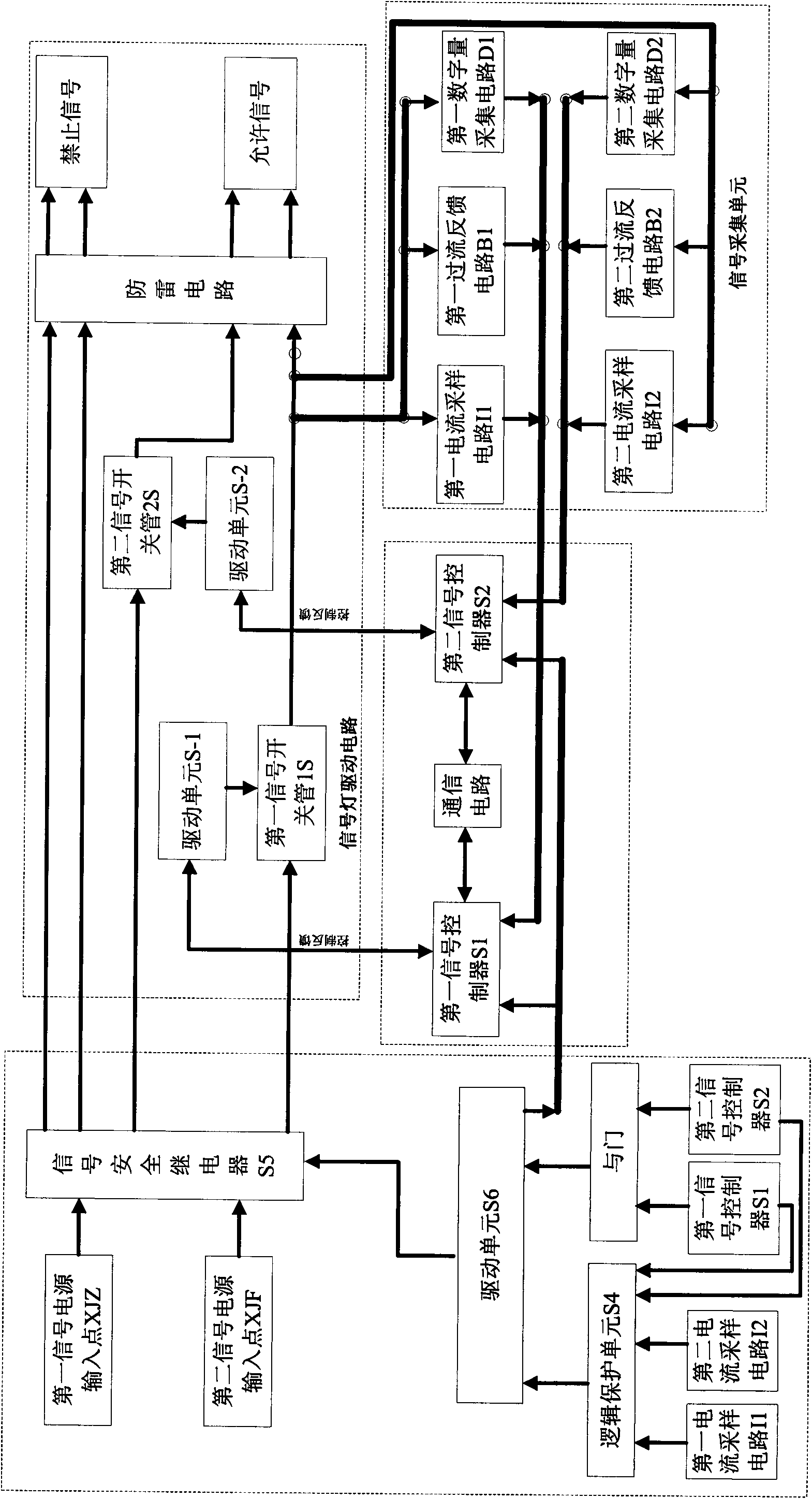
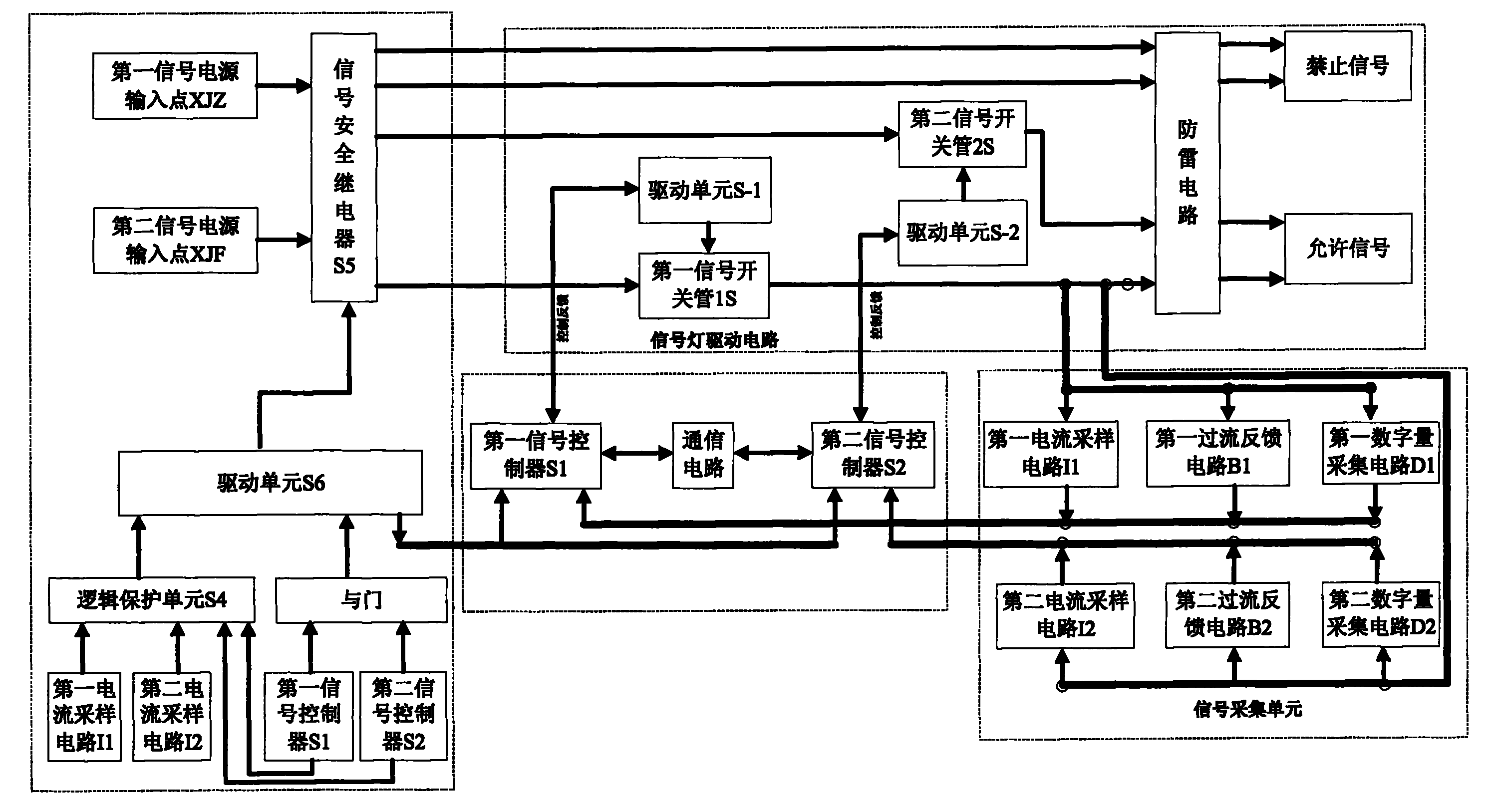
[0028] The specific implementation of the signal execution unit of the computer interlocking system of the present invention will now be described with reference to the accompanying drawings.

[0029] like figure 1 and 2 As shown, the signal execution unit of the present invention includes first and second signal controllers S1 and S2, and a signal light control unit jointly controlled by the two. The signal light control unit corresponds to the signal light one by one; the signal execution The unit also includes a protection unit and a signal acquisition unit, and the protection unit includes a logic protection unit S4 and a signal safety relay S5. The first and second signal controllers S1 and S2 are connected through a communication circuit. It is explained here that the two are completely independent in control, and the communication circuit is only responsible for completing clock synchronization and does not involve affecting their respective outputs. Communication of ...


PUM


Abstract

The invention discloses a signal execution unit of a computer interlocking system and a working method thereof. The execution unit comprises a signal lamp control unit, a protective unit and a signal acquisition unit, wherein the protective unit comprises a logic protective unit and a signal safety relay; the logic protective unit receives first signal state information and second signal state information which is output by a first signal controller and a second controller respectively and represents the working state of each signal lamp control unit; the first and second signal controllers and the logic protective unit receive system feedback information acquired by the signal acquisition unit; the logic protective unit performs logical comparison on the first and second signal state information and the system feedback information through hardware, and outputs a signal lamp abnormal signal for controlling the signal safety relay according to a comparison result; and under the condition that the signal lamp abnormal signal is output, only the signal lamp abnormal signal is used for controlling the signal safety relay to ensure that the signal execution unit finishes fault oriented safety.

Description

technical field [0001] The invention relates to a station interlocking control system, in particular to a signal execution unit for controlling signal lamps and a working method thereof. Background technique [0002] The signal execution unit of station interlocking equipment is used to control various signal lights to perform corresponding actions. The coordinated use of different color light signals can provide various calibration indication information. Therefore, the correct lighting of each signal light is of great importance to railway safety. effect. [0003] In practical applications, if the signal lights display disorderly, the signal execution unit needs to perform fail-safe safety. Among them, the disorderly display phenomenon also includes the occurrence of "hostile signals" in the signal execution unit, for example, for the shunting signal In other words, a white light signal appears when a blue light signal is turned on, or two colored lights are turned on at ...

Claims


Application Information

Patent Timeline
IPC IPC(8): B61L23/00B61L5/18
Inventor 赵丽宏段磊王锁平项银芬沈拓何建宏刘宇驰李宪国韩冬
Owner 上海亨钧科技股份有限公司
Why Eureka
Try Eureka