Semi-open-type rotor

A semi-open rotor technology, applied in the direction of rotating equipment cleaning, cleaning heat transfer devices, damage protection, etc., can solve the problems of reduced life of the shaft, damage to the inner wall of the heat exchange tube, and large driving torque, so as to save material costs and strengthen the exchange rate. Thermal effects, performance-enhancing effects

Active Publication Date: 2010-12-15
BEIJING UNIV OF CHEM TECH
View PDF9 Cites 8 Cited by
  • Summary
  • Abstract
  • Description
  • Claims
  • Application Information

AI Technical Summary

Problems solved by technology

To sum up, the spiral bond has the following main disadvantages: (1) The bond is a whole, which directly scratches the heat transfer tube and damages the inner wall of the heat transfer tube; (2) When the fluid flows to push the bond to rotate, it requires a large driving torque and consumes more (3) The service life of the bearing used for single-end fixing is short; (4) The effect of field synergy enhanced heat transfer generated by the bond is not significant
But the disadvantage is that when a certain fluid passes through, the rotation speed of the rotor is determined by the helix angle of the flight. When the flight lead is small, the rotation speed of the rotor is fast, and the resistance to the fluid increases accordingly; in order to solve this problem , Chinese patent application number 200620172805.5, the title of the invention is "low flow resistance rotor with self-cleaning and enhanced heat transfer in the heat transfer tube", the device is composed of a rotor, a support frame and a connecting axis. The two ends of the axis are respectively fixed on the support frame, and multiple rotors are mounted on the connecting axis. The rotor is composed of a hollow shaft and blades. Each blade is inclined in the same shape as the hollow shaft. Adjacent blades are connected end to end. The fluid resistance of the structure is reduced, and the fluid passing performance is good, but its rotation speed is high, and the superposition of the axial force of the rotor exerts a large force on the pendant and the shaft, and the life of the shaft will be reduced. The degree of turbulence of the fluid is not high enough, the temperature difference between the central fluid in the heat exchange tube and the fluid in the boundary layer of the heat exchange tube is large, and it has not been realized that all the fluid in the heat exchange tube can have a good heat exchange effect with the shell medium. The radial width does not change in the axial direction, and the mixing degree of the central layer fluid and the laminar layer fluid in the heat exchange tube is not good enough, which limits the effect of the rotor's enhanced heat transfer and anti-scaling and descaling capabilities

Method used


Image

  • Semi-open-type rotor
  • Semi-open-type rotor
  • Semi-open-type rotor

Examples


Embodiment Construction

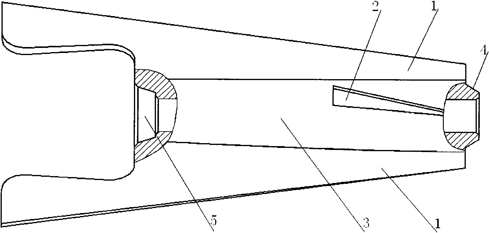
[0020] Such as Figure 7 As shown, the present invention relates to an implementation example of a semi-open rotor. A semi-open rotor of the present invention, a pendant 9 and a rotating shaft 10 are installed in the heat exchange tube 8. Several of the rotors are mounted on two On the rotating shaft 10 between the hanging parts 9, the hanging parts 9 are fixed on both ends of the heat exchange tube 8, and the two ends of the rotating shaft 10 are respectively fixed on the hanging parts 9. On the shaft 3, the radial width of the main blade 1 changes in the axial direction, and the main blade 1 at the rear part of the rotor is provided with a suspended part 6, which can cooperate with the front end of the adjacent rotor.

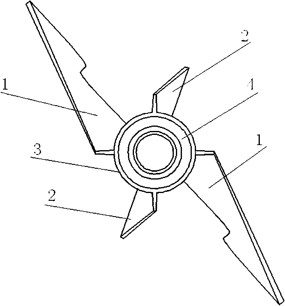
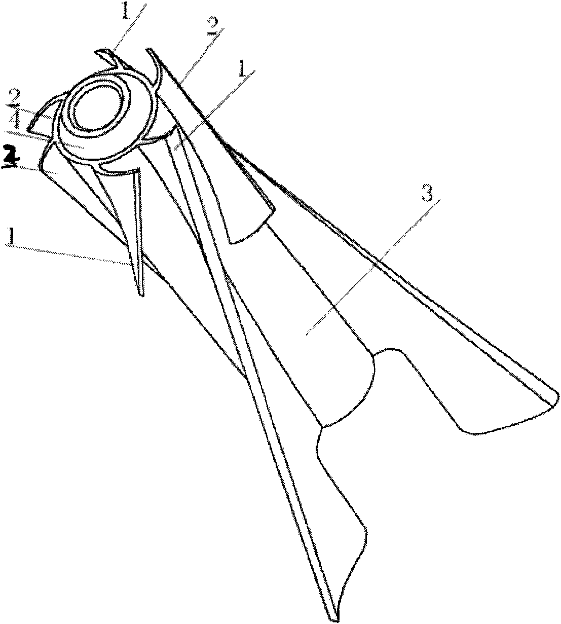
[0021] Figure 1 to Figure 6 As shown, the cross-sectional shape of the hollow shaft 3 of the rotor of the present invention is a hollow cylinder; figure 1 and figure 2 Among them, two main blades 1 and two auxiliary blades 2 are arranged on the rotor hol...


PUM


Abstract

The invention provides a semi-open-type rotor which comprises a hollow shaft, a main blade and an auxiliary blade. The main blade and the auxiliary blade are arranged on the outer surface of the hollow shaft, the main blade has a longer axial length, the main blade at the rear end of the rotor is suspended to form a semi-open-type structure which is axially overlapped with the front end of an adjacent rotor in use, radially forms a gap or is radially matched with the front end of an adjacent rotor, the radial width of the front part of the main blade on the hollow shaft is smaller than the radial width of the rear part, the front part of the main blade has a small rotary diameter, the rear end part of the main blade has a larger rotary external diameter, and the auxiliary blade is arranged at the front end of the rotor and has a shorter axial length. The front part of the main blade of the rotor has the small rotary diameter to take the effect of spoiling central fluid of a heat exchange pipe and scattering the central fluid around, the rear part of the main blade, which has the larger rotary external diameter, has good flow spoiling effect on the boundary layer fluid of an inner laminar flow of the heat exchange pipe and can adjust the rotor-driving torque of the fluid by adjusting the axial length of the auxiliary blade so as to enhance the fluid-adapting performance of the rotor.

Description

technical field [0001] The invention relates to an interpolation element for enhancing heat transfer, anti-scaling and descaling in heat exchange tubes of equipment such as shell-and-tube heat exchangers and heat exchange reactors. Background technique [0002] At present, energy saving and emission reduction is a key technology that the whole world attaches great importance to. It is applied to many heat exchangers in many fields such as petroleum, chemical industry, thermal power, nuclear power, metallurgy, light industry, aviation devices and ship vehicles. Among them The most widely used is the shell-and-tube heat exchanger, but the inner wall of these heat exchange tubes generally has layered dirt, which leads to an increase in the resistance of the fluid in the pipeline, and in severe cases, the pipeline will be blocked, and the heat transfer performance will be greatly reduced; The dirt in the heat pipe will seriously reduce the heat transfer efficiency and cause a ma...

Claims


Application Information

Patent Timeline
Patent Type & Authority Applications(China)
IPC IPC(8): F28F13/12F28F13/02F28F19/00F28G3/00
Inventor 杨卫民赵本华阎华丁玉梅何雪涛
Owner BEIJING UNIV OF CHEM TECH
Why Eureka
Try Eureka