System, method, and apparatus for magnetic resonance RF-field measurement

一种磁共振成像、设备的技术,应用在医疗成像系统领域,能够解决限制临床应用等问题

Active Publication Date: 2010-12-22
GENERAL ELECTRIC CO
View PDF5 Cites 18 Cited by
  • Summary
  • Abstract
  • Description
  • Claims
  • Application Information

AI Technical Summary

Problems solved by technology

However, the specific absorption rate (SAR) associated with such techniques can limit the clinical application of such techniques at high magnetic fields

Method used


Image

  • System, method, and apparatus for magnetic resonance RF-field measurement
  • System, method, and apparatus for magnetic resonance RF-field measurement
  • System, method, and apparatus for magnetic resonance RF-field measurement

Examples


Embodiment Construction

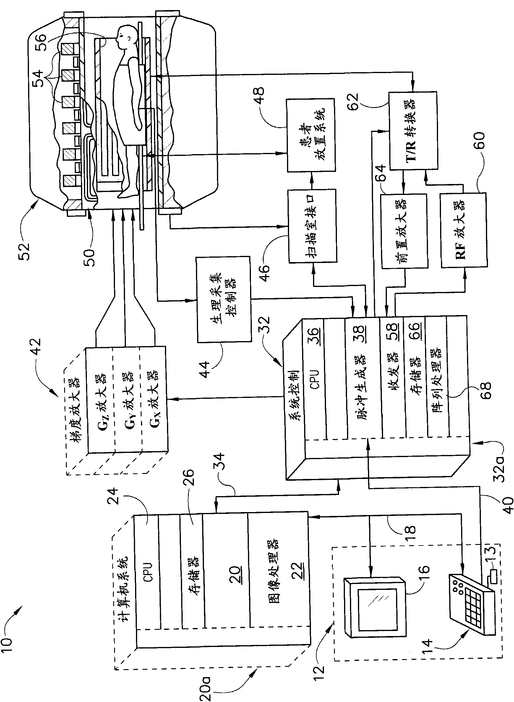
[0019] refer to figure 1 , shows the main components of an exemplary magnetic resonance imaging (MRI) system 10 incorporating an embodiment of the present invention. Operation of the system is controlled from an operator console 12 including a keyboard or other input device 13 , a control panel 14 and a display screen 16 . Console 12 communicates via link 18 with a separate computer system 20 that enables an operator to control the generation and display of images on display screen 16 . Computer system 20 includes a plurality of modules that communicate with each other through backplane 20a. These modules include an image processor module 22, a CPU module 24 and a memory module 26 which may include a frame buffer for storing an array of image data. The computer system 20 is linked to an archival media device, a persistent or backup memory device or a network for storage of image data and programs, and communicates with a separate system control 32 via a high speed serial lin...


PUM


Abstract

The name of the invention is 'system, method and apparatus for magnetic resonance RF-field measurement'. An apparatus, system, and method including a magnetic resonance imaging (MRI) apparatus includes a magnetic resonance imaging (MRI) system having a plurality of gradient coils positioned about a bore of a magnet, and an RF transceiver system and an RF switch controlled by a pulse module to transmit RF signals to an RF coil assembly to acquire MR images, and a computer. The computer is programmed to apply a first off-resonant radio frequency (RF) pulse at a first frequency different than the resonant frequency to a plurality of nuclei excited at a resonant frequency, acquire a first signal from the plurality of nuclei after application of the first off-resonant RF pulse, determine a phase shift from the first signal based on the first off-resonant RF pulse, determine a B1 field based on the phase shift, and store the B1 field on a computer readable storage medium.

Description

technical field [0001] The present invention relates generally to medical imaging systems, and more particularly to B 1 field determination. Background technique [0002] Substances such as human tissue are subjected to a uniform magnetic field (polarization field B 0 ), the individual magnetic moments of the spins in the tissue try to align with this polarization field, but precess around it in random order at their characteristic Larmor frequency. If the substance or tissue is subjected to a magnetic field in the x-y plane and close to the Larmor frequency (excitation field B 1 ), then the net aligned moment or "longitudinal magnetization" M z Can be rotated or "flipped" into the x-y plane to produce a net transverse magnetic moment M t . In the excitation signal B 1 After termination, a signal is emitted by the excited spins and this signal can be received and processed to form an image. [0003] When using these signals to generate images, a magnetic field gradien...

Claims


Application Information

Patent Timeline
Patent Type & Authority Applications(China)
IPC IPC(8): A61B5/055
CPCG01R33/246G01R33/583A61B5/055A61B5/0402A61B5/318
Inventor L·I·萨科利克M·W·富格尔F·维辛格I·汉库
Owner GENERAL ELECTRIC CO
Why Eureka
Try Eureka