
Induction quenching method of gearshift shaft of change gear case

An induction quenching and shifting fork technology, applied in the field of gearbox shifting fork shaft processing, can solve the problems of increased brittleness of parts, improper handling, brittle fracture, etc., to meet the performance requirements, simple structure and process, and high production efficiency Effect

Active Publication Date: 2013-08-14
FAW GROUP
View PDF3 Cites 0 Cited by
  • Summary
  • Abstract
  • Description
  • Claims
  • Application Information

AI Technical Summary

Problems solved by technology

[0002] In the 10TA transmission independently developed by FAW, there are three types of shift fork shafts. In order to improve wear resistance, part of the journal, a V-shaped ring groove, two sides of three continuous grooves and the bottom of the groove are required to be strengthened by induction hardening. Due to the complex structural size of the quenching area of ​​the part and the characteristics of induction heating, it is very difficult to realize this process. The main technical difficulties are: ①The effective hardened layer is continuously distributed on both sides of the notch and at the bottom of the groove; ②With a Φ5.6mm through hole The three continuous grooves are easy to harden because the wall thickness is very thin, which increases the brittleness of the parts, resulting in brittle fracture; ③ improper handling, prone to overburning and melting at the sharp corners of the groove
With the traditional process method, the induction hardening quality of this part cannot meet the technical conditions stipulated in the drawings, nor can it meet the performance requirements

Method used


Image

  • Induction quenching method of gearshift shaft of change gear case
  • Induction quenching method of gearshift shaft of change gear case
  • Induction quenching method of gearshift shaft of change gear case

Examples


Embodiment 1

[0012] Shift fork shaft 1, reverse gear

[0013] Shift fork shaft 2, 3, gear

[0014] Shift fork shaft 4, 5, gear

[0015] Part number: 1702041-A7G

[0016] 1702036-A7G

[0017] 1702031-A7G

[0018] Induction hardening technical requirements:

[0019] Material: 45A08M-12.2

[0020] Pre-heat treatment: quenching and tempering 223~254HBW according to A08M-7.1

[0021] Induction hardening area: surface hardness 56~62HRC according to A08M-8.2

[0022] Effective hardened layer depth DS450HV51.0~3.0.


PUM


Abstract

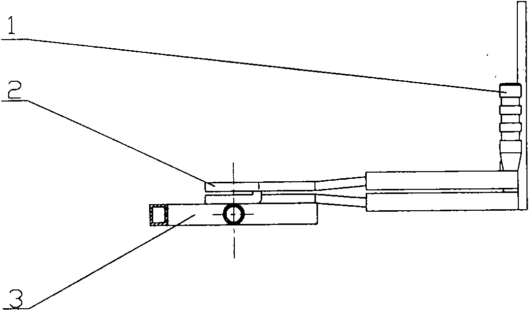
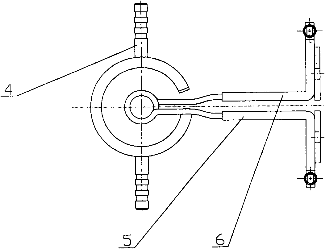
The invention relates to an induction quenching method of a gearshift shaft of a change gear case, which is characterized in that an inductor is a double-coil series inductor which is provided with an effective coil, wherein the effective coil is made of Phi 5*0.5 red copper tube and has the inner diameter of Phi 23 and the turn space of 2mm, a water spray ring is made of 12*10*1.5 red copper tube, has the inner diameter of 75mm and height of 12mm and is fixed below the effective coil, and therefore, the distribution of effective hardening layers can be controlled effectively, the overburningand melting of partial pointed parts or through quenching at thin wall part can be avoided, induction quenching of the two sides and the bottom of a groove and continuous distribution of the effective hardening layers are realized; the induction quenching quality of the spare part reaches the induction quenching technical requirement required by product drawings and using property requirement. The inductor has simple structure and process, the passing ability of various spare parts is strong, and the productivity is high. The method can be promoted and applied to the induction quenching of similar spare parts.

Description

Technical field: [0001] The invention relates to an induction hardening method for a shift fork shaft of a gearbox, which is applied to the field of processing the shift fork shaft of a gearbox. Background technique: [0002] In the 10TA transmission independently developed by FAW, there are three types of shift fork shafts. In order to improve wear resistance, part of the journal, a V-shaped ring groove, two sides of three continuous grooves and the bottom of the groove are required to be strengthened by induction hardening. Due to the complex structural size of the quenching area of ​​the part and the characteristics of induction heating, it is very difficult to realize this process. The main technical difficulties are: ①The effective hardened layer is continuously distributed on both sides of the notch and at the bottom of the groove; ②With a Φ5.6mm through hole The three continuous grooves are easy to harden because the wall thickness is very thin, which increases the br...

Claims


Application Information

Patent Timeline
Patent Type & Authority Patents(China)
IPC IPC(8): C21D9/00C21D1/10
CPCY02P10/25
Inventor 姜波孙彤雷崔凯李航宇王宏郇宜梅高霞毛春力
Owner FAW GROUP
Learn More