Synchronous towing, pushing and tunneling device of underground box culvert or pipeline construction

A technology for pipeline construction and box culverts, applied in pipeline laying and maintenance, tunnels, pipes/pipe joints/pipe fittings, etc. It can solve the problem of increasing the workload and corresponding costs of rectification, the deviation of the machine head from the travel axis, and the pin holes of pipe joints. In order to improve the culvert section increase, the construction excavation length is longer, and the floor space can be saved.

Inactive Publication Date: 2010-12-22
SHANGHAI GUANGLIAN ENVIRONMENTAL & GEOTECHNICAL ENG CO LTD
View PDF4 Cites 11 Cited by
  • Summary
  • Abstract
  • Description
  • Claims
  • Application Information

AI Technical Summary

Problems solved by technology

Existing pipe jacking construction devices are all composed of jacking jacks and tunneling heads. This construction device has the following defects: 1) Since the driving power of the machine head and pipe joints is completely provided by the jacking jacks in the starting shaft, its construction The excavation length is short, and in order to provide sufficient horizontal backing force and overcome the jacking resistance, the thickness of the structural wall of the departure shaft and the thickness of the back reinforcement of the departure shaft are relatively large, which is not suitable for narrow construction sites; 2) Due to the It is heavy, so it is easy for the machine head to deviate from the travel axis during the excavation process in soft soil areas, especially when the machine head goes out and enters the hol

Method used


Image

  • Synchronous towing, pushing and tunneling device of underground box culvert or pipeline construction
  • Synchronous towing, pushing and tunneling device of underground box culvert or pipeline construction
  • Synchronous towing, pushing and tunneling device of underground box culvert or pipeline construction

Examples


Embodiment Construction

[0021] The embodiments of the present invention will be described in further detail below in conjunction with the accompanying drawings, but the present embodiments are not intended to limit the present invention, and any similar structures and similar changes of the present invention should be included in the protection scope of the present invention.

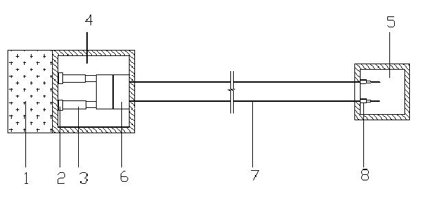
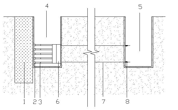
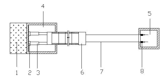
[0022] Such as Figure 1-Figure 4 As shown, the embodiment of the present invention provides a synchronous traction and jacking excavation device for underground buried box culvert or pipeline construction. Two working wells are built at both ends of the design axis of the box culvert or pipeline, which are respectively departure shafts 4 and the receiving shaft 5; it is characterized in that: the device includes a push jack group 3, a tunneling head 6, a pulling jack group 8 and a plurality of stay cables 7;

[0023] The push jack group 3 is installed in the departure shaft 4;

[0024] A cable reaction force wall is provided...


PUM


Abstract

The invention provides a synchronous towing, pushing and tunneling device of underground box culvert or pipeline construction, relating the technical field of building construction machinery. The invention solves the technical problems of increasing suitability for a construction field, tunneling length and construction work efficiency. The synchronous towing, pushing and tunneling device comprises a push jack set, a tunneling machine head, a pull jack set and a plurality of cables, wherein the push jack set is arranged in a starting well, a cable reactive wall is arranged in a receiving well, the pull jack set is arranged on the cable reactive wall, at least four horizontal directional holes are drilled between the starting well and the receiving well along a designed axis direction, the cables are respectively laid into the horizontal directional holes, one end of each cable is connected and fixedly locked with the pull jack set in the receiving well, the other end of each cable is fixedly connected with the head of the tunneling machine head, and a cable self-locking mechanism which is used for stopping the cables is arranged on the pull jack set. The synchronous towing, pushing and tunneling device of underground box culvert or pipeline construction is suitable for various sizes of reinforced concrete or steel structure culverts or pipelines with rectangular and circular sections.

Description

technical field [0001] The invention relates to the technology of building construction machinery, in particular to the technology of a synchronous traction and jacking driving device for underground box culvert or pipeline construction. Background technique [0002] As a trenchless technology, the pipe jacking method has the advantage of little disturbance to the ground, so it is widely used in the current underground pipeline construction. Existing pipe jacking construction devices are all composed of jacking jacks and tunneling heads. This construction device has the following defects: 1) Since the driving power of the machine head and pipe joints is completely provided by the jacking jacks in the starting shaft, its construction The excavation length is short, and in order to provide sufficient horizontal backing force and overcome the jacking resistance, the thickness of the structural wall of the departure shaft and the thickness of the back reinforcement of the depart...

Claims


Application Information

Patent Timeline
IPC IPC(8): E21D9/04F16L1/036
Inventor 李淑海方兆昌杨述起顾荣森张志勇王中兵
Owner SHANGHAI GUANGLIAN ENVIRONMENTAL & GEOTECHNICAL ENG CO LTD
Why Eureka
Try Eureka