
Method for simultaneously recovering water and latent heat in high-humidity flue gas and heat pump device

A heat pump device, high humidity technology, applied in heat pump device, recovery of water and latent heat, simultaneous recovery of water and latent heat in high humidity flue gas, can solve problems such as unfavorable utilization of low temperature waste heat, increase of heat transfer links, increase of equipment investment, etc. Achieve good energy saving, reduce heat transfer links, and reduce the cost of absorbent

Inactive Publication Date: 2010-12-22
INST OF ENGINEERING THERMOPHYSICS - CHINESE ACAD OF SCI
View PDF0 Cites 28 Cited by
  • Summary
  • Abstract
  • Description
  • Claims
  • Application Information

AI Technical Summary

Problems solved by technology

In some occasions where there is a large amount of low-temperature waste heat, such as the flue gas of the air humidification cycle, the waste heat temperature is low and the amount is large, and there is also a requirement for water recovery. The traditional closed circulation system increases the heat transfer link. For low temperature Waste heat utilization is unfavorable, and it also increases equipment investment

Method used


Image

  • Method for simultaneously recovering water and latent heat in high-humidity flue gas and heat pump device
  • Method for simultaneously recovering water and latent heat in high-humidity flue gas and heat pump device
  • Method for simultaneously recovering water and latent heat in high-humidity flue gas and heat pump device

Examples


Embodiment Construction

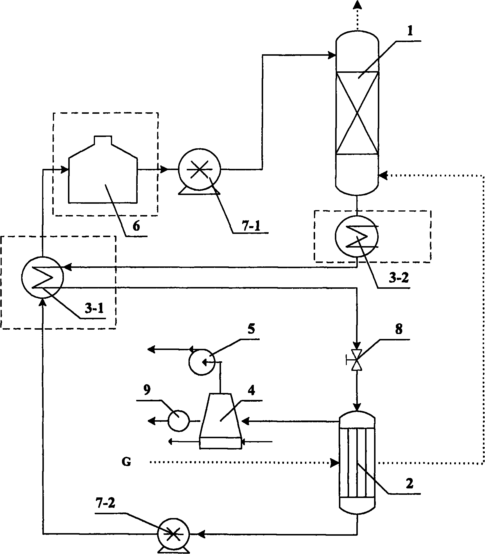
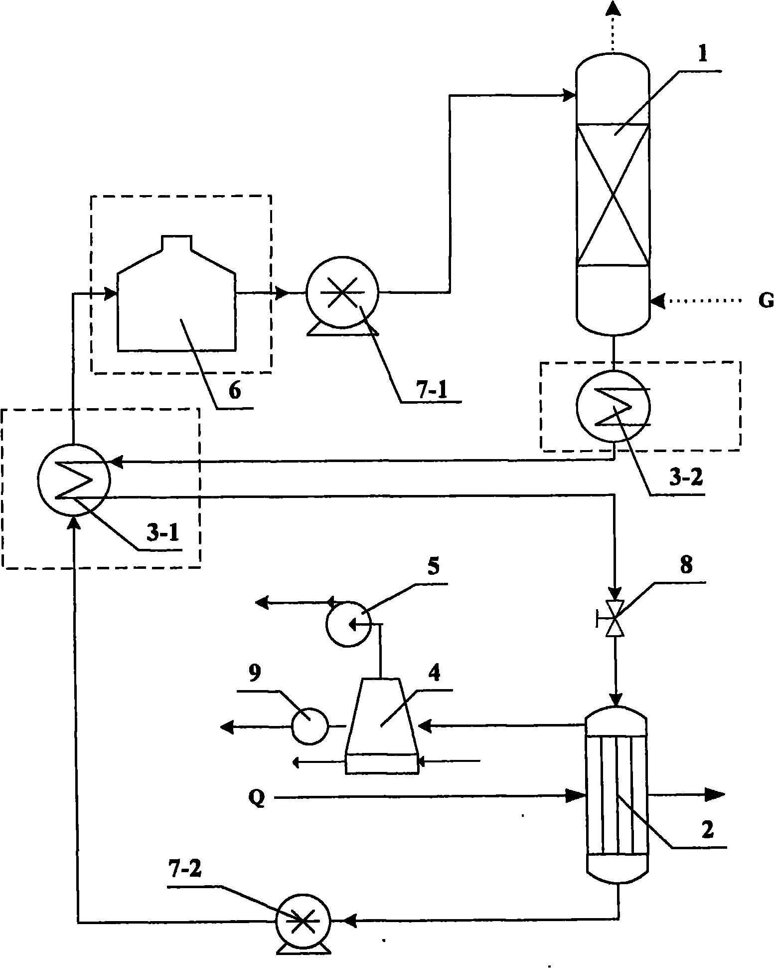
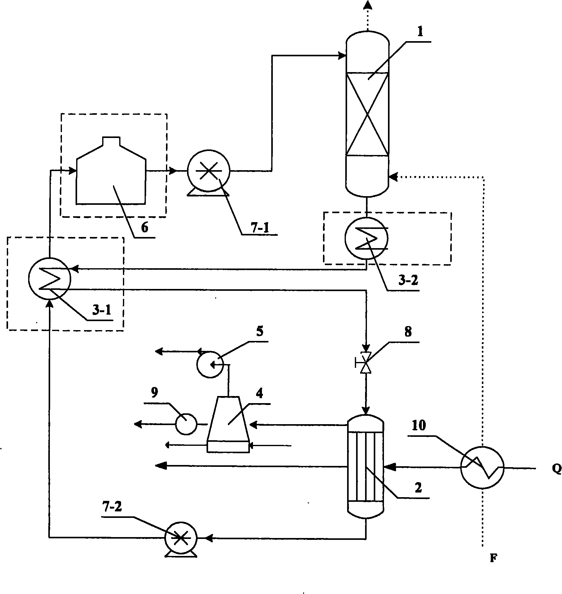
[0043] A method for simultaneously recovering water and latent heat in high-humidity flue gas of the present invention is an open cycle second-type absorption heat pump, including an absorption unit, a regeneration unit, a heat recovery unit, and a water recovery unit. Absorbent adopts calcium chloride aqueous solution. Such as Figure 5 , the flue gas enters the absorption unit, and the concentrated solution absorbs the water in the flue gas in the absorption unit to become a high-temperature dilute solution (latent heat is released when the water is absorbed); the high-temperature dilute solution passes through the heat recovery unit to release heat recovery and becomes a lower temperature dilute solution Then enter the regeneration unit; the recovered heat is sent to the heating pipe network in the heating unit; the dilute solution in the regeneration unit is heated and evaporated by the heat source to become a concentrated solution, and the concentrated solution enters the...


PUM


Abstract

The invention discloses a method for simultaneously recovering water and latent heat in high-humidity flue gas and a heat pump device, relating to the technique of energy-saving equipment. A heat exchanger is arranged in an absorber of the heat pump device, the top of the absorber is provided with a flue gas discharging pipe, the bottom of the absorber is provided with a dilute solution outlet, the side surface of the bottom is provided with a gas inlet pipe, the side surface of the top is provided with a concentrated solution inlet, and a concentrated solution pipeline is communicated with a spray head at the inner upper part of a cavity; the top of a regenerator is provided with a dilute solution inlet, the bottom of the regenerator is provided with a concentrated solution pipeline outlet, a gas-liquid heat exchanger is arranged in the regenerator, and an inlet and an outlet of the gas-liquid heat exchanger are communicated with a flue gas pipe; the flue gas pipe is communicated with the gas inlet pipe at the bottom of the absorber after passing through the regenerator; the bottom of the absorber is communicated with the regenerator through a dilute solution pipeline, in which a regulating valve is arranged; and the regenerator runs under negative pressure, and the bottom of the regenerator is communicated with the absorber through the concentrated solution pipeline, in which a solution pump is arranged. The method and the device directly recover the water and the latent heat in the flue gas and have the advantages of equipment simplification, better energy saving, environmental protection and economic benefit.

Description

technical field [0001] The invention relates to the technical field of energy-saving equipment, and is a method and a heat pump device for simultaneously recovering water and latent heat in high-humidity flue gas, especially suitable for recovering water and latent heat in high-humidity flue gas produced by gas, oil-fired boilers and air humidification cycles . Background technique [0002] The flue gas produced by gas, oil-fired boilers and air humidification cycle contains a lot of water. According to calculation, 1m 3 The combustion of natural gas produces more than 1.6kg of water, and the air humidification cycle will also add a large amount of water to the cycle. According to data, the moisture content of the flue gas emitted by the air humidification cycle can reach 0.1-0.20 (moisture content It refers to the ratio of the mass of water contained in the gas to the mass of dry gas). The humidity of flue gas emitted by these cycles is much higher than that of ordinary c...

Claims


Application Information

Patent Timeline
Patent Type & Authority Applications(China)
IPC IPC(8): F25B15/06F25B27/02F25B37/00C02F9/10C02F1/04
CPCY02B30/625Y02A30/274
Inventor 路源肖云汉徐震魏璠
Owner INST OF ENGINEERING THERMOPHYSICS - CHINESE ACAD OF SCI
Learn More