
Optical measuring device with high reflectivity and high transmissivity

An optical measurement, high transmission technology, applied in the field of optical measurement devices, high transmittance optical measurement devices, and high reflectance, it can solve the problems of high reflectance and high transmittance of optical components that cannot be accurately measured, and achieve stable power and use. handy effect

Active Publication Date: 2010-12-22
CHINA NORTH IND NO 205 RES INST
View PDF5 Cites 25 Cited by
  • Summary
  • Abstract
  • Description
  • Claims
  • Application Information

AI Technical Summary

Problems solved by technology

[0005] The technical problem to be solved by the present invention is to provide an optical measurement device with high reflectance and high transmittance for the problem that the high reflectance and high transmittance of optical elements in the prior art cannot be accurately measured. Specifically, the measurement The device is based on single reflection measurement method, combined with laser power stabilization technology, dual optical path measurement technology and precision detection technology, so as to realize the measurement of high reflectance and high transmittance of optical components

Method used


Image

  • Optical measuring device with high reflectivity and high transmissivity
  • Optical measuring device with high reflectivity and high transmissivity
  • Optical measuring device with high reflectivity and high transmissivity

Examples


Embodiment Construction

[0026] The present invention will be further described in detail below in conjunction with the accompanying drawings and preferred embodiments.

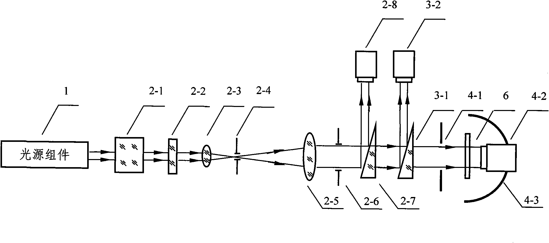
[0027] as figure 1 As shown, the optical measurement system provided by the preferred embodiment of the present invention is composed of a light source assembly 1 , a laser power stabilization unit 2 , a monitoring system 3 , a detection system 4 and a computer 5 .

[0028] The light source assembly 1 contains a He-Ne laser and its power supply, a YAG laser and its power supply, which are used for the measurement of reflectance and transmittance at 632.8nm wavelength and 1064nm wavelength respectively. The output power of the He-Ne laser is 15mW, and the stability of the laser is better than 1.0%. The output power of the YAG laser is 100mW, the divergence angle is 1mrad, and the stability is better than 2.5%.

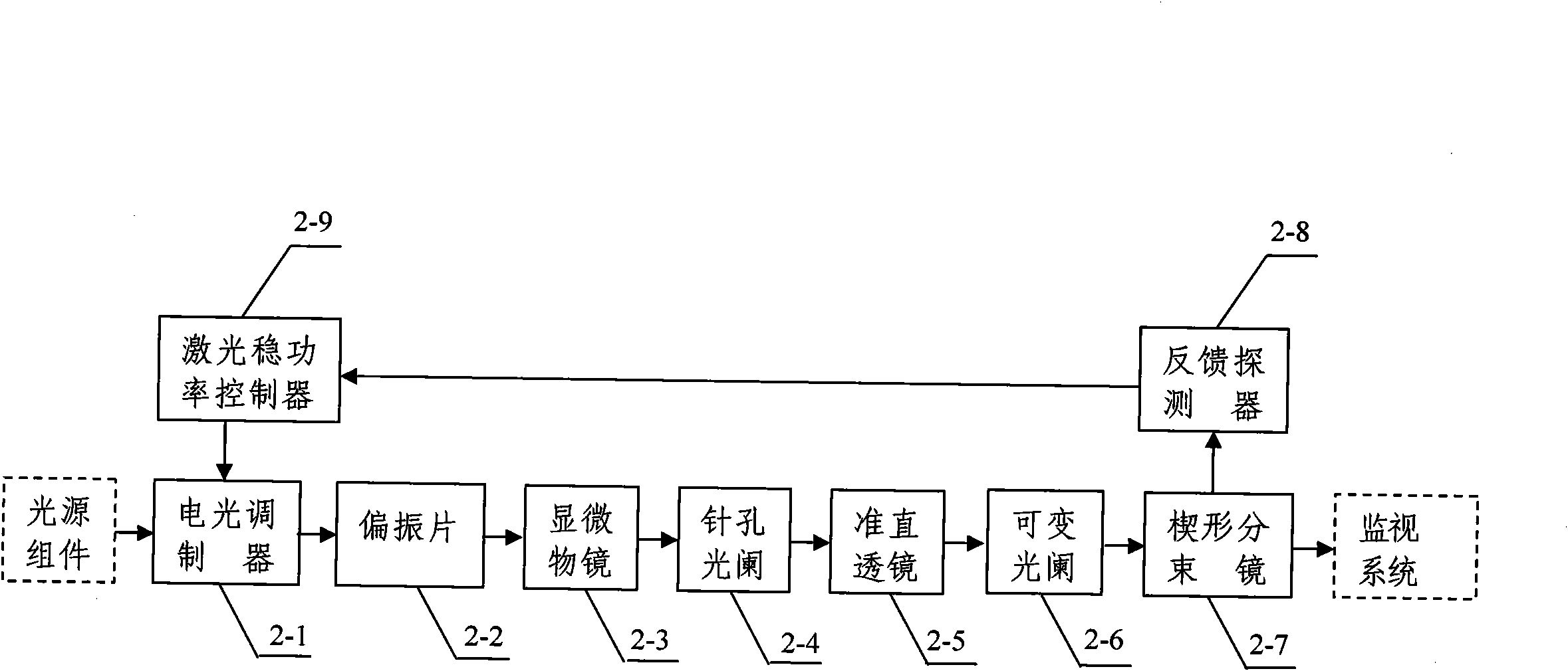
[0029] according to image 3 As shown, the laser power stabilizing unit 2 includes an electro-optic modulator, a polarizer ...


PUM

PropertyMeasurementUnit
Wavelength rangeaaaaaaaaaa
Apertureaaaaaaaaaa
Apertureaaaaaaaaaa

Abstract

The invention discloses an optical measuring device with high reflectivity and high transmissivity, belonging to the field of optical measuring tests. The device comprises an optical source assembly, a laser power stabilizing unit, a monitoring system with a wedge-shaped beam splitter and a trap detector, a detection system with an integrating sphere detector, and a computer with a measuring software package. Laser output by the optical source assembly forms a stable beam with instability less than 0.01% after passing through the laser power stabilizing unit. The beam is divided into two beams by the wedge-shaped beam splitter, wherein one beam is received by the trap detector, and the other beam is received by the integrating sphere detector after passing through a tested sample. The outputs of the trap detector and the integrating sphere detector are sent to the computer. The computer correspondingly processes a received signal and finally gives the measurement results of the reflectivity and the transmissivity of the tested sample. The invention solves the accurate measurement problem of high reflectivity and high transmissivity of an optical element, and the measurement range is 99.5-99.99%. The invention has the characteristics of high measurement accuracy, good repeatability and broad application prospect.

Description

technical field [0001] The invention belongs to the field of optical metrology and testing, and relates to an optical measurement device, in particular to a high reflectance and high transmission device based on a single reflection measurement method combined with laser power stabilization technology, dual optical path measurement technology and precision detection technology. than optical measuring devices. Background technique [0002] Reflectance and transmittance are important parameters for evaluating optical properties such as optical components and optical films. With the continuous progress and development of science and technology, laser technology and optical thin film technology have developed rapidly. Especially in recent years, the emergence of high-tech projects such as laser gyroscopes requires higher and higher reflectance and transmittance of laser optical components. Already higher than 99.95% (higher than 95.00% is called high reflectance, high transmitta...

Claims


Application Information

Patent Timeline
IPC IPC(8): G01M11/02
Inventor 侯西旗范纪红秦艳杨斌俞兵李宏光
Owner CHINA NORTH IND NO 205 RES INST
Learn More