Rotary positioning mechanism of LED die bonder
A technology of positioning mechanism and die bonding machine, which is applied in the direction of electrical components, circuits, semiconductor devices, etc., can solve the problems of wafer vibration and low wafer positioning accuracy, and achieves convenient installation and debugging, easy remote control, and difficult wear effect
- Summary
- Abstract
- Description
- Claims
- Application Information
AI Technical Summary
Problems solved by technology
Method used
Image
Examples
Embodiment 2
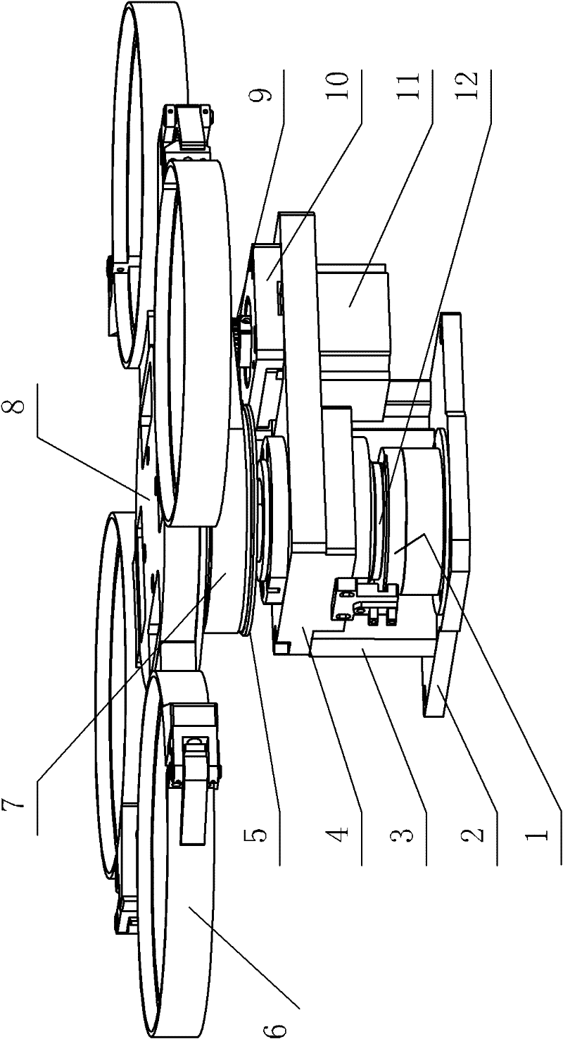
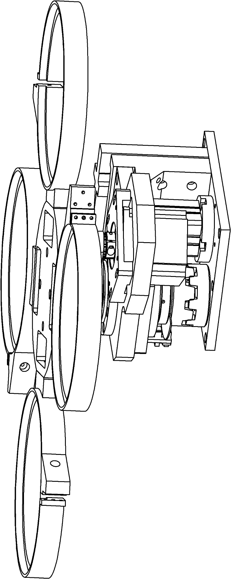
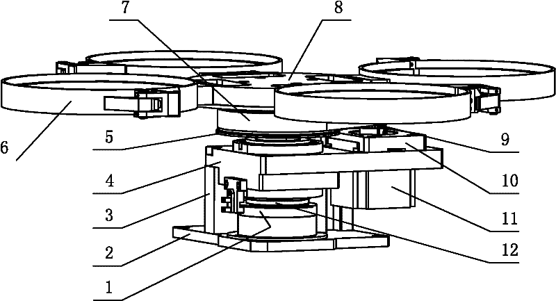
[0022] The electromagnetic brake provided in this embodiment is an energized electromagnetic eddy current brake, and the turntable shaft brake assembly is an electromagnetic brake assembly, including an energized brake electromagnetic brake and its mounting plate 2, and the electromagnetic brake 1 is installed on the turntable shaft 12. To reduce the braking torque and structural size. The electromagnetic brake is an electromagnetic eddy current brake with a dynamic friction torque of 0.5Kg / m and a static friction torque of 0.6Kg / m. The rotary positioning mechanism is installed on the wafer XY workbench, which is directly driven by the wafer XY workbench. When the suction nozzle at the tip of the swing arm of the welding head picks up the wafer from the wafer tray 6 to the bonding position and replaces the wafer on the next wafer tray 6 after bonding, the stepping motor 11 drives the turntable shaft 12 to rotate, driven by the transmission belt 7 The indexing synchronous wheel...
Embodiment 3
[0025] The electromagnetic brake provided in this embodiment is an energized electromagnetic friction brake, and the turntable shaft brake assembly is an electromagnetic brake assembly, including an energized brake type electromagnetic brake and its mounting plate 2, and the electromagnetic brake 1 is installed on the turntable shaft 12 to Reduced braking torque and structural size. Electromagnetic brake 1 is an electromagnetic friction brake with a dynamic friction torque of 0.5Kg / m and a static friction torque of 0.6Kg / m. The rotary positioning mechanism is installed on the wafer XY workbench, and the work is directly driven by the wafer XY workbench. , when the suction nozzle at the tip of the welding head swing arm picks up the wafer from the wafer tray 6 to the solid crystal position and replaces the wafer of the next wafer tray 6 after the bonding is completed, the stepping motor 11 drives the turntable shaft 12 to rotate, and the drive belt 7 The indexing synchronous wh...
Embodiment 4
[0028] The electromagnetic brake provided in this embodiment is a power-off braking type electromagnetic powder brake, and the turntable shaft brake assembly is an electromagnetic brake assembly, including a power-off braking type electromagnetic brake and its mounting plate 2, and the electromagnetic brake is installed on the turntable shaft 12 , to reduce the braking torque and structural size. The electromagnetic brake is an electromagnetic powder brake with a dynamic friction torque of 0.5Kg / m and a static friction torque of 0.6Kg / m. The rotary positioning mechanism is installed on the wafer XY workbench, which is directly driven by the wafer XY workbench. When the suction nozzle at the tip of the welding head’s swing arm picks up the wafer from the wafer tray 6 to the bonding position and replaces the next wafer on the wafer tray 6 after bonding, the stepping motor 11 drives the turntable shaft 12 to rotate, driven by the transmission belt 7 The indexing synchronous wheel...
PUM
 Abstract
Description
Claims
Application Information
 - R&D
- Intellectual Property
- Life Sciences
- Materials
- Tech Scout
- Unparalleled Data Quality
- Higher Quality Content
- 60% Fewer Hallucinations
Browse by: Latest US Patents, China's latest patents, Technical Efficacy Thesaurus, Application Domain, Technology Topic, Popular Technical Reports.
© 2025 PatSnap. All rights reserved.Legal|Privacy policy|Modern Slavery Act Transparency Statement|Sitemap|About US| Contact US: help@patsnap.com


