Absorption heating and refrigerating all-in-one machine taking high-temperature gas as heat source

A high-temperature gas and absorption heat pump technology, applied in the field of energy technology applications, can solve the problems that gaseous waste heat resources cannot be fully utilized, latent heat cannot be fully utilized, etc., and achieve the effect of improving energy utilization efficiency and reducing temperature

Active Publication Date: 2013-08-21
TSINGHUA UNIV +1
View PDF5 Cites 0 Cited by
  • Summary
  • Abstract
  • Description
  • Claims
  • Application Information

AI Technical Summary

Problems solved by technology

[0002] In many process systems or energy systems, there are often a large number of gaseous waste heat resources such as flue gas that cannot be fully utilized in winter, and additional investment is required to configure additional equipment for waste heat utilization in summer
For example, in a gas-fired combined heat and power system, the exhaust temperature of the flue gas is above 100°C. This part of the flue gas not only takes away most of the sensible heat, but also does not fully utilize its latent heat. This is because the exhaust gas The temperature of the flue gas is limited by the heat requirements of the user, and it can no longer be reduced by using a conventional heat exchanger; in summer, in order to utilize the waste heat resources of the flue gas, it is necessary to add a separate waste heat utilization device

Method used


Image

  • Absorption heating and refrigerating all-in-one machine taking high-temperature gas as heat source
  • Absorption heating and refrigerating all-in-one machine taking high-temperature gas as heat source
  • Absorption heating and refrigerating all-in-one machine taking high-temperature gas as heat source

Examples


Embodiment 1

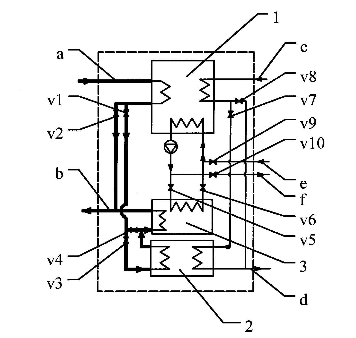
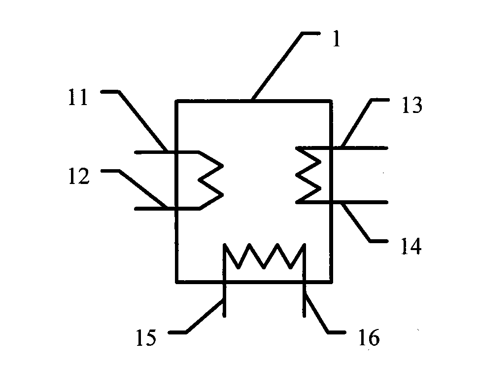
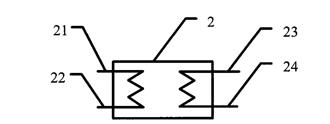
[0033] Figure 5 It is a schematic flow chart of the first connection mode in the heating condition of the present invention. The first valve v1, the third valve v3, the fifth valve v5, the sixth valve v6, the seventh valve v7 open, the second valve v2, the fourth valve v4, the eighth valve v8, the ninth valve v9, the tenth valve v10 closure. The high-temperature gas is flue gas at 530°C. The high-temperature flue gas first enters the absorption heat pump unit 1 from the high-temperature gas pipeline a from the generator inlet 11 as a driving heat source, and the high-temperature flue gas is heated and concentrated in the generator of the absorption heat pump unit 1. LiBr The solution is discharged from the generator outlet 12 of the absorption heat pump 1 when the temperature drops to 210°C, and the flue gas at 210°C enters the high-temperature gas-water heat exchanger 2 from the gas side inlet 22 of the high-temperature heat exchanger as a heating source, and cools down to ...

Embodiment 2

[0035] Figure 6 It is a schematic flow chart of the second connection mode in the heating condition of the present invention. The first valve v1, the fourth valve v4, the fifth valve v5, the sixth valve v6, the eighth valve v8 open, the second valve v2, the third valve v3, the seventh valve v7, the ninth valve v9, the tenth valve v10 closure. The high-temperature gas is flue gas at 530°C. The high-temperature flue gas first enters the absorption heat pump unit 1 from the high-temperature gas pipeline a from the generator inlet 11 as a driving heat source, and the high-temperature flue gas is heated and concentrated in the generator of the absorption heat pump unit 1. LiBr The solution is discharged from the generator outlet 12 of the absorption heat pump 1 when the temperature drops to 130°C, and the flue gas at 130°C enters the low-temperature gas-water heat exchanger 3 through the gas side inlet 32 ​​of the low-temperature heat exchanger, and is discharged from the The ex...

Embodiment 3

[0037] Figure 7 It is a schematic flow chart of the connection mode of refrigeration working conditions in the present invention. The second valve v2, the eighth valve v8, the ninth valve v9, and the tenth valve v10 are open, the first valve v1, the third valve v3, the fourth valve v4, the fifth valve v5, the sixth valve v6, and the seventh valve v7 closure. The high-temperature gas is flue gas at 530°C. The high-temperature flue gas first enters the absorption heat pump unit 1 from the high-temperature gas pipeline a from the generator inlet 11 as a driving heat source, and the high-temperature flue gas is heated and concentrated in the generator of the absorption heat pump unit 1. LiBr The solution is discharged from the generator outlet 12 of the absorption heat pump 1 through the exhaust pipe b when the temperature is lowered to 130°C; on the chilled water side, the chilled water return water at 12°C passes through the chilled water return pipe e through the evaporator inl...


PUM


Abstract

The invention belongs to the field of the application of energy source technology and particularly relates to an absorption heating and refrigerating all-in-one machine taking high-temperature gas as a heat source. A unit comprises accessories such as an absorption heat pump, a high temperature gas-water heat exchanger, a low temperature gas-water heat exchanger, a plurality of connecting pipelines, a valve and the like; and a connecting pipeline system consists of a gas side pipeline, a refrigerated water side pipeline and a cooling water side pipeline and has a heating mode and a refrigerating mode. The absorption heating and refrigerating all-in-one machine can make use of the heat of the high-temperature gas in a cascade way under a heating condition, so that the temperature of the gas side pipeline is lowered greatly, energy utilization efficiency is improved and the temperature of gas exhausted from an exhaust pipeline after heat exchange is lower than the temperature of water flowing into a cooling water side, which cannot be realized by the conventional heating unit; moreover, the absorption heating and refrigerating all-in-one machine has a refrigerating function in summer, so that two functions of one machine are realized.

Description

technical field [0001] The invention belongs to the application field of energy technology, in particular to an absorption heating and cooling integrated machine using high-temperature gas as a heat source. Background technique [0002] In many process systems or energy systems, there are often a large number of gaseous waste heat resources such as flue gas that cannot be fully utilized in winter, and additional investment is required to configure additional equipment for waste heat utilization in summer. For example, in a gas-fired combined heat and power system, the exhaust temperature of the flue gas is above 100°C. This part of the flue gas not only takes away most of the sensible heat, but also has not fully utilized its latent heat. This is because the exhaust gas The temperature of the flue gas is limited by the heat requirements of the user, and it can no longer be reduced by using a conventional heat exchanger; and in summer, in order to utilize the waste heat resou...

Claims


Application Information

Patent Timeline
Patent Type & Authority Patents(China)
IPC IPC(8): F25B29/00F25B27/02
CPCY02A30/274
Inventor 付林赵玺灵张世钢江亿
Owner TSINGHUA UNIV
Why Eureka
Try Eureka