
Method of micro cantilever beam sensor using functional carbon nano tubes as sensitive materials

A carbon nanotube and micro-cantilever technology, which is applied in the field of micro-nano sensors, can solve the problem that research on changes has not been reported, and achieves the effects of advanced methods, low cost and easy operation.

Active Publication Date: 2011-01-05
SHANGHAI INST OF MICROSYSTEM & INFORMATION TECH CHINESE ACAD OF SCI
View PDF3 Cites 21 Cited by
  • Summary
  • Abstract
  • Description
  • Claims
  • Application Information

AI Technical Summary

Problems solved by technology

Using mass-type (resonant) micro-cantilever devices as the detection platform, there are no reports on the corresponding changes in the mass of carbon nanotubes when they adsorb target substances.

Method used


Image

  • Method of micro cantilever beam sensor using functional carbon nano tubes as sensitive materials
  • Method of micro cantilever beam sensor using functional carbon nano tubes as sensitive materials
  • Method of micro cantilever beam sensor using functional carbon nano tubes as sensitive materials

Examples


Embodiment 1

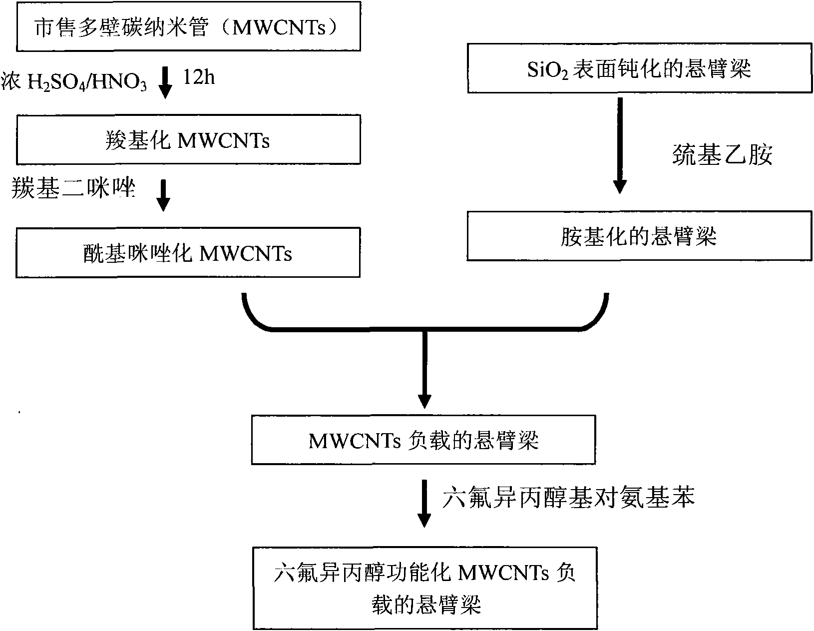
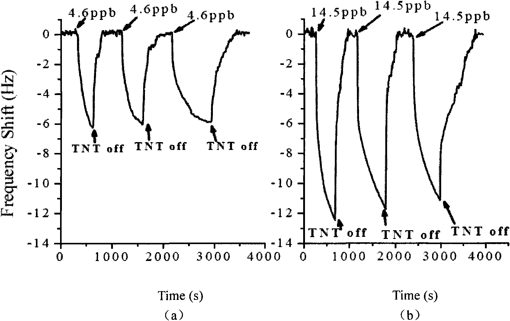
[0017] Embodiment 1: in combination with figure 1 with 2 The manufacturing method and detection characteristics of the MEMS sensor based on functionalized carbon nanotubes that can be used for ppb (that is, the volume ratio is one billionth) level TNT vapor detection are described in detail.

[0018] Weigh 100mg of commercial multi-walled carbon nanotubes (abbreviated as MWCNTs, purchased from Shenzhen Nanometer Port), put it into a 125ml glass bottle, add 60ml of concentrated sulfuric acid (98% by mass) and 20ml of concentrated nitric acid (98% by mass) 70%), sonicated for 12 hours to generate carboxyl sites available for modification on the surface of MWCNTs. Dilute the above-mentioned mixed acid solution containing MWCNTs to 1000ml with deionized water, then settle for 12 hours, and remove the supernatant. The deposited MWCNTs were collected, diluted with deionized water, and the diluted solution was filtered with a polytetrafluoroethylene membrane with a pore size of 1 m...

Embodiment 2

[0022] Embodiment 2: NH that can be used for ppm level based on functionalized carbon nanotubes 3 Detection of MEMS sensors

[0023] The pretreatment of MWCNTs and its fixation on the gold surface of MEMS devices are the same as in Example 1. During detection, a certain amount of p-Aminobenzoic acid (PABA) was firstly weighed and dissolved in deionized water to prepare a solution with a concentration of 1 mg / ml. The gold surface modified with MWCNTs is immersed in the solution, and the acyl imidazoles on the side walls of MWCNTs can react with the amino groups of PABA. Finally, the MEMS device is rinsed with deionized water and dried with nitrogen, which can be used for the NH3 test on the order of ppm (that is, the volume ratio is one millionth). Its detection result is similar to embodiment 1.


PUM

PropertyMeasurementUnit
Sensitivityaaaaaaaaaa

Abstract

The invention relates to a manufacturing method of a micro cantilever beam sensor using functional carbon nano tubes as sensitive materials, belonging to the field of a micro-nano sensor. The method is characterized by comprising the following steps: using multi-walled carbon nano tubes as manufacturing materials of the sensor, and pretreating with strong acid to form reaction-active points which can be functionally modified on the surfaces of the multi-walled carbon nano tubes; then, fixing the multi-walled carbon nano tubes onto the gold surface of the MEMS sensor according to the molecular self-assembly technology; and finally, carrying out functional group modification again on the carbon nano tubes fixed on the gold surface of the MEMS sensor according to chemical properties of target gas to be detected (for example, a certain hydrogen bonding effect and the like exist between ammonia gas and carboxyl as well as formaldehyde and amino group) based on the molecular design, and enabling the sensor to be used for the detection of special target gas.

Description

technical field [0001] The invention relates to a method for manufacturing a micro-cantilever beam sensor using functionalized carbon nanotubes as sensitive materials, and belongs to the field of micro-nano sensors. Background technique [0002] As an important biochemical detection method, high-sensitivity gas sensor has a wide range of applications in environmental monitoring, food industry, medical diagnosis, national security, etc. Among the numerous gas sensor categories, the gas sensor based on MEMS (micro-electro-mechanical system) technology is one of the research hotspots. The representative of the MEMS sensor is the micro-cantilever beam sensor, which has the advantages of simple structure, easy fabrication, high sensitivity, and flexible use. Generally, there are two working modes of the micro-cantilever sensor: dynamic and static. Among them, the dynamic (resonant) micro-cantilever works by detecting the drop in resonance frequency (Δf) caused by the mass adsor...

Claims


Application Information

Patent Timeline
IPC IPC(8): B81C1/00G01N33/00G01N33/22
Inventor 李昕欣许鹏程于海涛徐铁刚李俊刚
Owner SHANGHAI INST OF MICROSYSTEM & INFORMATION TECH CHINESE ACAD OF SCI
Learn More