
Copper cooling wall with reinforced piping structure

A technology to strengthen the structure and stave, applied in the direction of cooling device, furnace cooling device, furnace cooling, etc., can solve the problems of reducing the overall strength of the copper stave, the depth of the welding groove is not deep enough, and cracks are easy to occur, so as to control the manufacturing cost , Improve the stress situation and avoid the effect of cracks

Active Publication Date: 2011-01-05
SHANTOU HUAXING METALLURGICAL EQUIP CO LTD
View PDF4 Cites 8 Cited by
  • Summary
  • Abstract
  • Description
  • Claims
  • Application Information

AI Technical Summary

Problems solved by technology

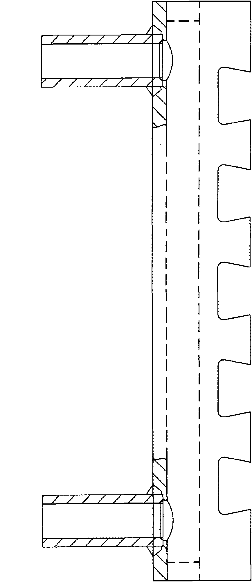
[0004] like figure 1 As shown, in the existing copper stave, its water pipes (inlet pipe and outlet pipe) are usually inserted into the inlet or outlet of the cooling water channel, and then welded on the cold surface. When the water pipe is subjected to external force, only the weld seam is stressed, so it is easy to produce cracks, causing water leaks
Under the premise that the wall thickness of the copper stave is constant, the opening of the cooling water channel will reduce the overall strength of the copper stave, especially at the welds between the inlet pipe, the outlet pipe and the cold surface, because the cold surface of the copper stave body reaches the cooling water The distance of the channel is usually short, so the depth of the welding groove is not deep enough, which leads to the poor strength of the weld. After being subjected to a large external force for a long time, cracks are more likely to occur, resulting in water leakage, and even from the weld. the whole break

Method used


Image

  • Copper cooling wall with reinforced piping structure
  • Copper cooling wall with reinforced piping structure
  • Copper cooling wall with reinforced piping structure

Examples


Embodiment 1

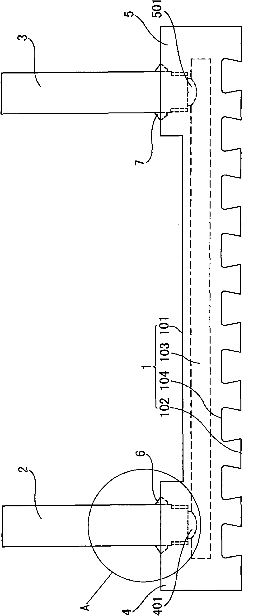
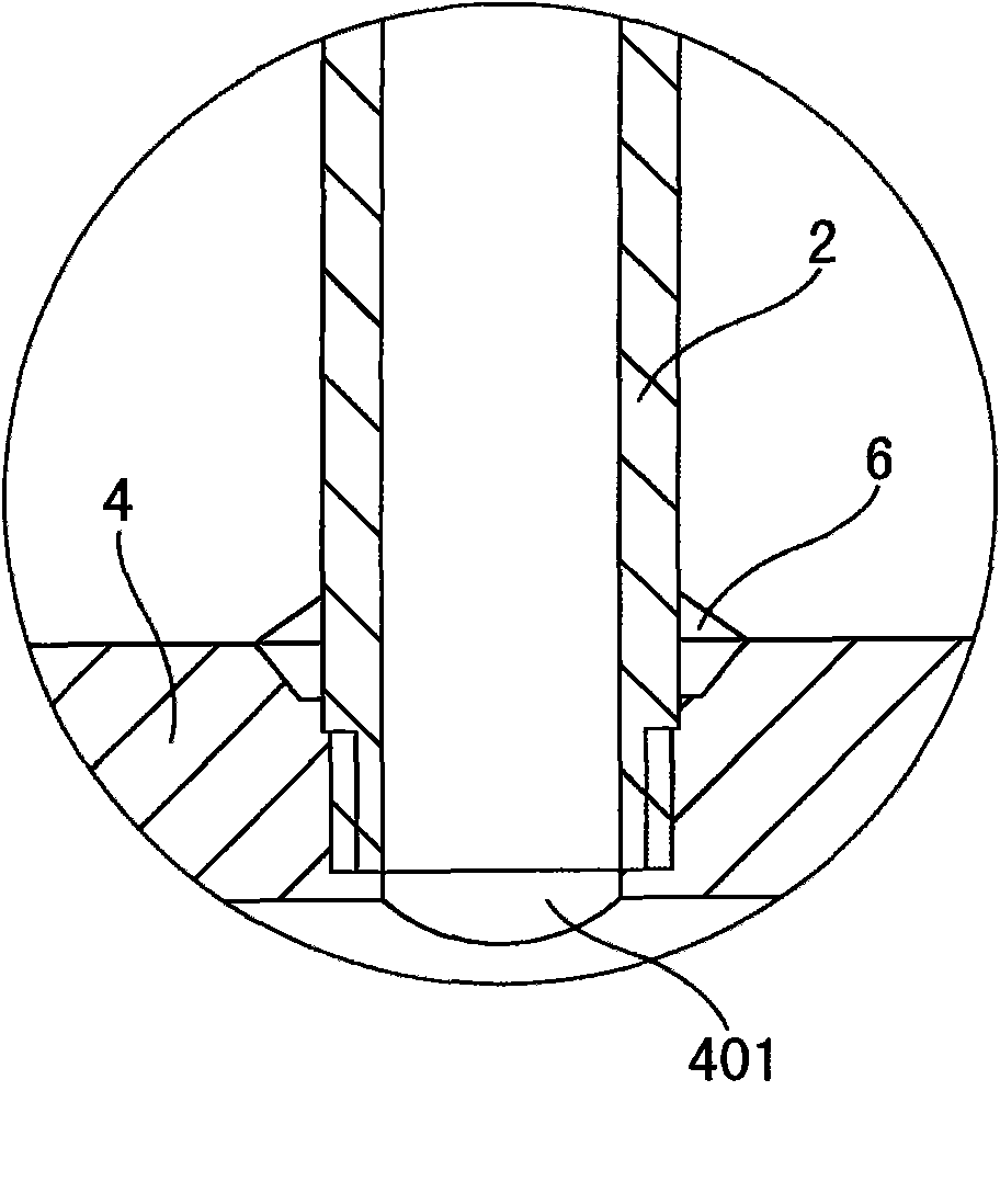
[0026] Such as Figure 2-4 As shown, a copper stave with pipe strengthening structure in this embodiment includes a copper stave body 1, three water inlet pipes 2 and three water outlet pipes 3, and three cooling water passages 103 are opened in the copper stave body 1 to feed Water pipe 2 connects the inlet of corresponding cooling water channel 103 on the cold surface 101 of copper stave body 1, and water outlet pipe 3 connects the corresponding cooling water channel 103 outlet on the cold surface 101 of copper stave body 1, and the heat of copper stave body 1 The surface 102 is provided with at least two dovetail grooves 104 parallel to each other for hanging slag, and also includes protrusions. The bumps include a first bump 4 and a second bump 5, the first bump 4 is arranged on the cold surface 101 of the copper stave body 1, and the first bump 4 is located above the inlet of the cooling water channel 103, The first bump 4 is provided with a first connecting hole 401 tha...

Embodiment 2

[0034] Such as Figure 5 As shown, the difference between the copper stave of a kind of pipe reinforcement structure in this embodiment and embodiment 1 is:

[0035] The distance from the cold surface 101 of the copper stave body 1 to the cooling water channel 103 is 15 mm.

[0036] The first protruding block and the second protruding block are integrated to form a complete protruding block without a groove. There is also no dovetail on the hot side. The disadvantage of this solution is that it consumes more copper, so the cost is higher.

Embodiment 3

[0038] The difference between the copper stave of a pipe strengthening structure in the present embodiment and the embodiment 1 is:

[0039] The first bump 4 and the second bump 5 are respectively connected to the copper stave body 1 by screws.

[0040] The distance from the cold surface 101 of the copper stave body 1 to the cooling water channel 103 is 25 mm.

[0041] The strength of the weld seam of this scheme is increased, but when the outside of the water inlet pipe 2 and the water outlet pipe 3 are subjected to external forces, due to the long-term stress between the first bump 4, the second bump 5 and the copper stave body 1, it is easy to If it is too large, gaps will appear, resulting in water leakage.


PUM

PropertyMeasurementUnit
lengthaaaaaaaaaa

Abstract

The invention provides a copper cooling wall with a reinforced piping structure. The copper cooling wall comprises a copper cooling wall body, at least one water inlet pipe and at least one water outlet pipe, wherein at least one cooling water channel is reserved in the copper cooling wall body; the water inlet pipe is welded on the cool surface of the copper cooling wall body, and is connected with the inlet of the cooling water channel; the water outlet pipe is welded on the cool surface of the copper cooling wall body, and is connected with the outlet of the cooling water channel; the water inlet pipe is inserted into the inlet of the cooling water channel, and is in threaded connection with the inner wall of the inlet of the cooling water channel; and the water outlet pipe is inserted into the outlet of the cooling water channel and is in threaded connection with the inner wall of the outlet of the cooling water channel. The copper cooling wall has the advantages of increasing stress points of the water pipe, and improving the stress condition of the water pipe to ensure that the stress of the water pipe is more uniform and a welding seam is hard to destroy; and because of lugs, the quality and the strength of the welding seam can be effectively improved, the consumption of copper can be greatly reduced, and the manufacturing cost of the copper cooling wall can be effectively controlled on the premise of ensuring the performance.

Description

technical field [0001] The present invention relates to a cooling device of a blast furnace, and more specifically relates to a copper stave with pipe reinforcement structure. Background technique [0002] The cooling device of the blast furnace is mainly divided into two types: the first type is a cooling plate inserted into the furnace body of the blast furnace for spot cooling of the furnace wall; the second type is covered on the inner wall of the blast furnace shell to perform surface cooling of the furnace wall cooling wall. In order to adapt to the longevity of the blast furnace, the staves used in the blast furnace are constantly updated. From the perspective of the material used, it has developed from cast iron staves and steel staves to copper staves with high thermal conductivity. Copper staves have cast copper staves, forged or rolled copper plate drilled staves. Among them, forged or rolled copper staves are widely used for their dense metallographic structur...

Claims


Application Information

Patent Timeline
Patent Type & Authority Applications(China)
IPC IPC(8): C21B7/10
CPCC21B7/106F27D2009/0048F27D1/12F27D2009/0059F27D9/00C21C5/4646F27D2009/0013
Inventor 佘京鹏李立鸿李上吉许领舜沈大伟
Owner SHANTOU HUAXING METALLURGICAL EQUIP CO LTD
Learn More