Low NOx rotational flow coal dust combustion device of industrial boiler

A technology for pulverized coal combustion and industrial boilers, applied in burners, combustion chambers, combustion methods, etc., can solve the problems of high pollutant emissions and low combustion efficiency of industrial boilers

Inactive Publication Date: 2011-01-05
SHANGHAI JIAO TONG UNIV
View PDF8 Cites 16 Cited by
  • Summary
  • Abstract
  • Description
  • Claims
  • Application Information

AI Technical Summary

Problems solved by technology

[0004] The present invention aims at the above-mentioned deficiencies in the prior art, and provides a low-NOx swirl pulverized coal combustion device for industrial boilers. Combining the combustion mode of the chamber combustion furnace, the pulverized coal combustion technology is proposed on the industrial boiler, and the grate in the industrial boiler is Remove it, install the lower furnace with heat insulation, ...

Method used


Image

  • Low NOx rotational flow coal dust combustion device of industrial boiler
  • Low NOx rotational flow coal dust combustion device of industrial boiler
  • Low NOx rotational flow coal dust combustion device of industrial boiler

Examples


Embodiment 1

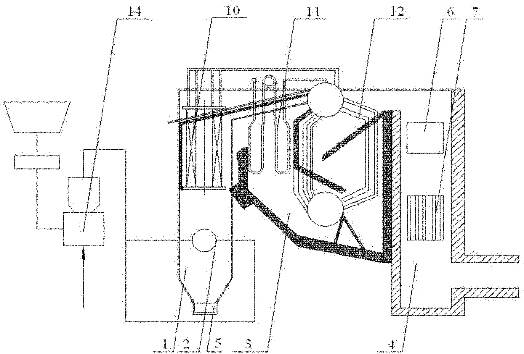
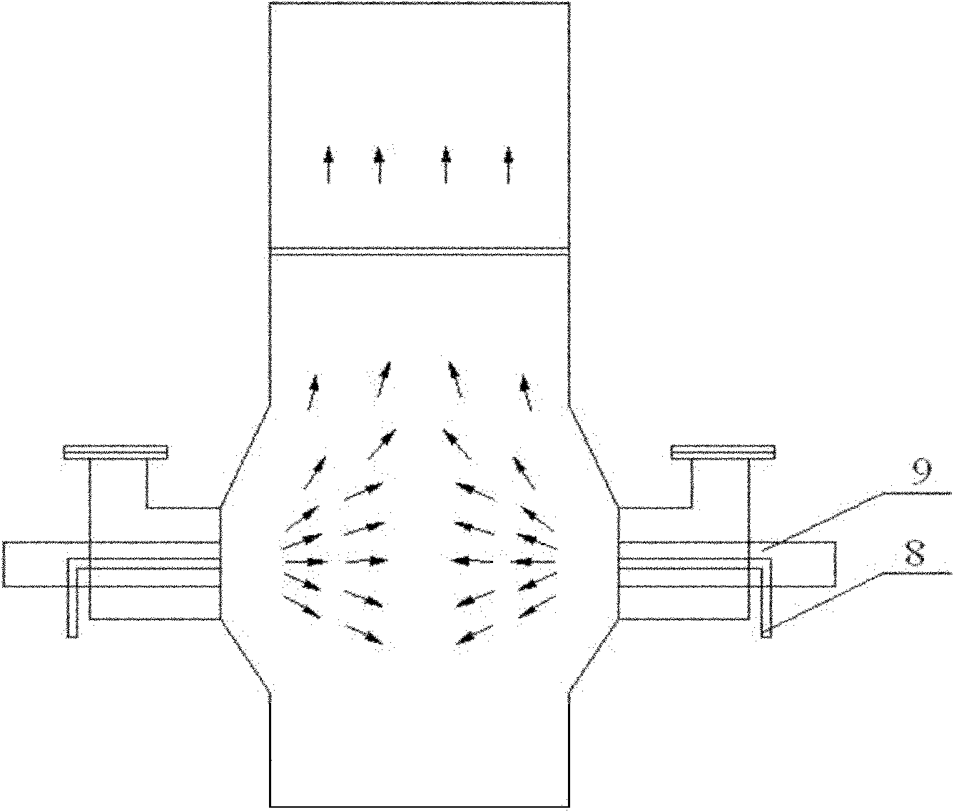
[0026] Such as figure 1 and image 3 As shown, this embodiment includes: furnace 1, swirl pulverized coal burner 2, burnout chamber 3, tail flue 4, ash hopper 5, economizer 6 and air preheater 7, wherein: furnace 1 is divided into The lower part of the adiabatic furnace 1 and the upper part of the water-cooled furnace 1, the adiabatic furnace 1 is located at the lower part of the furnace 1 and has a protruding structure on the front and rear walls or the left and right walls, the swirl pulverized coal burner 2 is respectively installed on the left and right walls of the adiabatic furnace 1, and the ash hopper 5 It is located at the lower part of the adiabatic furnace 1 to collect the ash after pulverized coal combustion. The water-cooled furnace 1 is equipped with a water-cooled wall 10 to absorb radiant heat and convective heat to heat the steam-water mixture from the economizer 6. The burnout chamber 3 is located in the furnace 1 The upper outlet of the upper outlet, the ta...

Embodiment 2

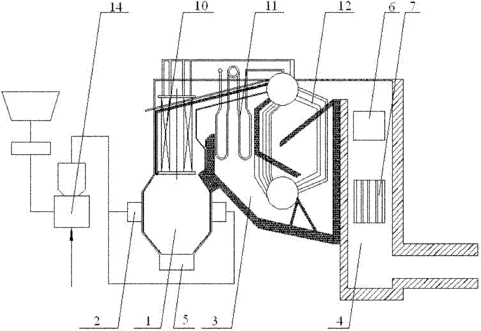
[0042] This embodiment includes: furnace 1, swirl pulverized coal burner 2, burnout chamber 3, tail flue 4, ash hopper 5, economizer 6 and air preheater 7, wherein: furnace 1 is divided into the lower heat insulation The furnace 1 and the upper water-cooled furnace 1, the adiabatic furnace 1 is located at the lower part of the furnace 1 and has a protruding structure on the front and rear walls, the swirl pulverized coal burners 2 are respectively installed on the front and rear walls of the adiabatic furnace 1, and the ash hopper 5 is located at the lower part of the adiabatic furnace 1 Collect the ash after pulverized coal combustion. The water-cooled furnace 1 is equipped with a water-cooled wall 10 to absorb radiant heat and convective heat to heat the steam-water mixture from the economizer 6. The burnout chamber 3 is located at the upper outlet of the furnace 1. The tail smoke The channel 4 is located at the outlet of the burnout chamber 3, and the economizer 6 and the ai...


PUM

PropertyMeasurementUnit
Outer diameteraaaaaaaaaa
Wall thicknessaaaaaaaaaa
Diameteraaaaaaaaaa

Abstract

The invention discloses a low NOx rotational flow coal dust combustion device of an industrial boiler, belonging to the technical field of industrial boilers. The low NOx rotational flow coal dust combustion device of the industrial boiler comprises a hearth, a rotational flow coal dust burner, a burnout chamber, a tail flue, an ash bucket, an economizer and an air preheater, wherein the hearth is divided into a lower heat-insulation hearth and an upper water cooled hearth; the heat-insulation hearth is positioned on the lower part of the hearth and is in a front-back wall protruded or left-right wall protruded structure; the rotational flow coal dust burner is respectively arranged on the left and right walls or the back and rear walls of the heat-insulation hearth; the ash bucket is positioned in the lower part of the heat-insulation hearth to collect the ash residue of combusted coal dust; the water cooled hearth is internally provided with a water cooled wall used for adsorbing radiant heat and convection heat so as to heat steam water mixture from the economizer; the burnout chamber is positioned on the upper outlet of the heart; the tail flue is positioned on the outlet of the burnout chamber; and the economizer and the air preheater are successively arranged in the tail flue. The invention realizes hedging combustion of the left and right walls or the back and rear walls of the rotational flow burner so as to realize stable and efficient combustion and realize the application of the low NOx combustion technology.

Description

technical field [0001] The invention relates to a device in the technical field of industrial boilers, in particular to a low NOx swirl pulverized coal combustion device for an industrial boiler. Background technique [0002] There are more than 500,000 industrial boilers in our country, which burn more than 400 million tons of coal every year, and the actual operating efficiency of most industrial boilers is about 70%. The energy utilization rate is low, the energy consumption is large, and the environmental pollution caused by smoke and dust emissions is very Seriously, the total amount of pollutant discharge is close to that of power plant boilers. In terms of fuel, my country's industrial boilers directly burn unwashed and processed raw coal, which cannot meet the coal quality requirements of various combustion equipment, resulting in poor combustion conditions in the furnace, smoke, SOx, NOx, CO in the flue gas If the concentration is large, not only the thermal efficie...

Claims


Application Information

Patent Timeline
IPC IPC(8): F23C5/08F23C3/00F23D1/02F22B31/08F23K1/00
CPCY02E20/34
Inventor 范卫东王俊超李友谊李宇
Owner SHANGHAI JIAO TONG UNIV
Why Eureka
Try Eureka