

Energy saver for base station machine room air conditioners
A technology for computer room air conditioners and energy-saving equipment, applied in lighting and heating equipment, space heating and ventilation, household heating, etc. Large, to achieve the effect of automatic fault repair
- Summary
- Abstract
- Description
- Claims
- Application Information
AI Technical Summary
Problems solved by technology
Method used
Image

Examples
Embodiment Construction
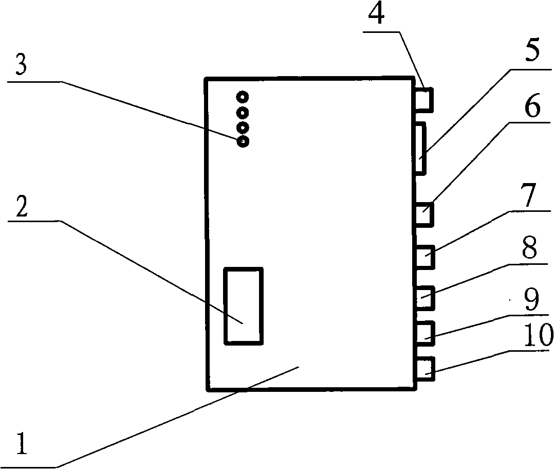
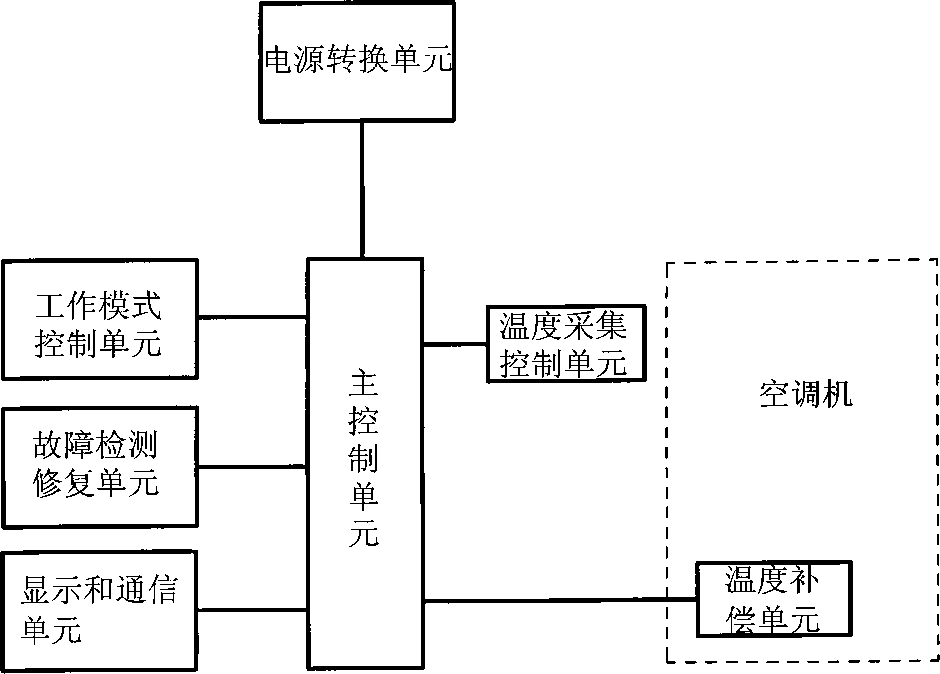
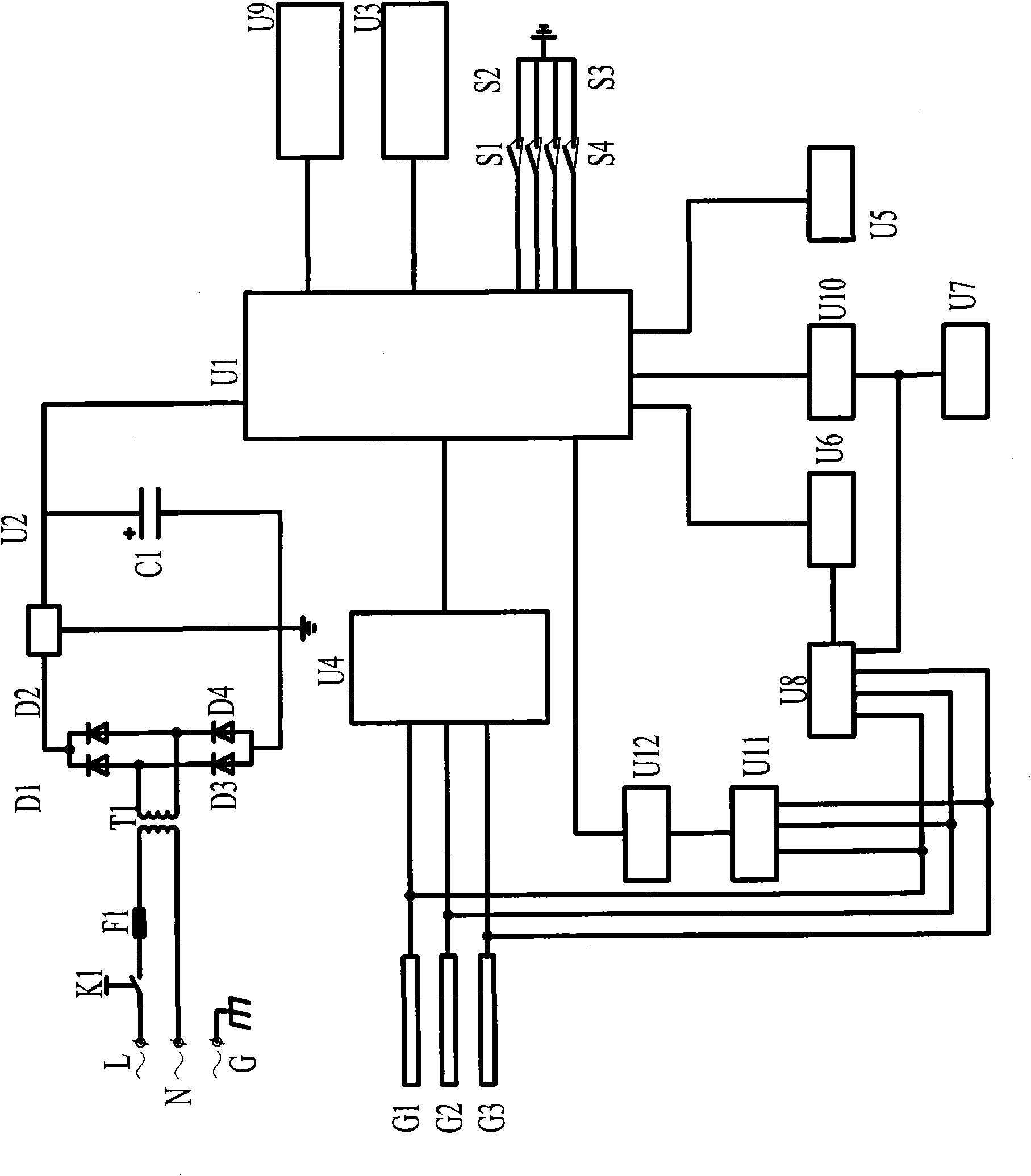
[0016] according to Figure 1~3The specific structure of the present invention will be described in detail. The air-conditioning energy-saving equipment in the base station computer room includes a housing 1 and a function key 3 composed of a liquid crystal display 2 (U3) on the housing 1, including a return key S1, an upward adjustment key S2, a downward adjustment key S3, and a confirmation key S4, and a power switch. 4. The room temperature sensor 9 is a transmission interface composed of a power line input interface 5, a data transmission interface 6, an air outlet temperature sensor interface 7, a semiconductor refrigerator interface 8, and a return air outlet temperature sensor interface 10, and is assembled in the housing 1. The main control unit with the single-chip microcomputer U1 and the external program memory U9 as the core and the automatic control loop formed by corresponding electronic components. The automatic control loop mainly includes a main control unit,...
PUM
 Abstract
Description
Claims
Application Information