
Preparation method for TiO2 nanometer rod array of dye sensitized solar cell

A technology of solar cells and nanorod arrays, which is applied in the field of preparation of TiO2 nanorod arrays, can solve the problems of large-area uniformity and difficulty in preparation, and achieve the effects of good repeatability, simple equipment, and convenient preparation

Inactive Publication Date: 2011-01-12
DALIAN INST OF CHEM PHYSICS CHINESE ACAD OF SCI
View PDF0 Cites 6 Cited by
  • Summary
  • Abstract
  • Description
  • Claims
  • Application Information

AI Technical Summary

Problems solved by technology

However, these chemistries are difficult to prepare large-area, uniform and reproducible TiO 2 nanorod array
So far, there have been no reports about the preparation of titania nanorod arrays by sputtering technology

Method used


Image

  • Preparation method for TiO2 nanometer rod array of dye sensitized solar cell
  • Preparation method for TiO2 nanometer rod array of dye sensitized solar cell
  • Preparation method for TiO2 nanometer rod array of dye sensitized solar cell

Examples


Embodiment 1

[0022] Example 1: Preparation method of anatase titanium dioxide nanorods with (220) preferred orientation

[0023] Place a clean ITO conductive glass substrate 70mm above the sputtering target in the vacuum chamber, and control the background vacuum to be less than 1×10 -3 Pa, without additional heating of the substrate.

[0024] Adjust various sputtering process parameters and perform sputtering. Before formal deposition, pre-sputter for 20 minutes. The specific process parameters are:

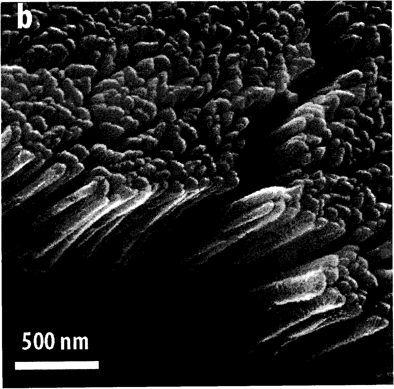
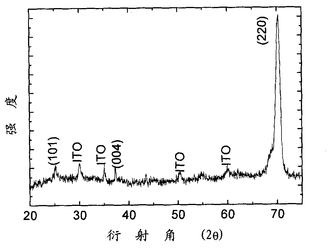
[0025] Reactive gas O 2 The air pressure is 2.5×10 -1 Pa, the pressure of the sputtering gas Ar is 2Pa, the sputtering current is 0.56A, the sputtering power is 235W, the sputtering time is 14 hours, and the TiO with a thickness of about 2 microns is obtained. 2 Nanorod arrays, such as figure 1 shown. Nanorod arrays have a very strong anatase (220) orientation, such as figure 2 shown.

Embodiment 2

[0026] Embodiment 2: the preparation method of the titania nanorod array of different diameters

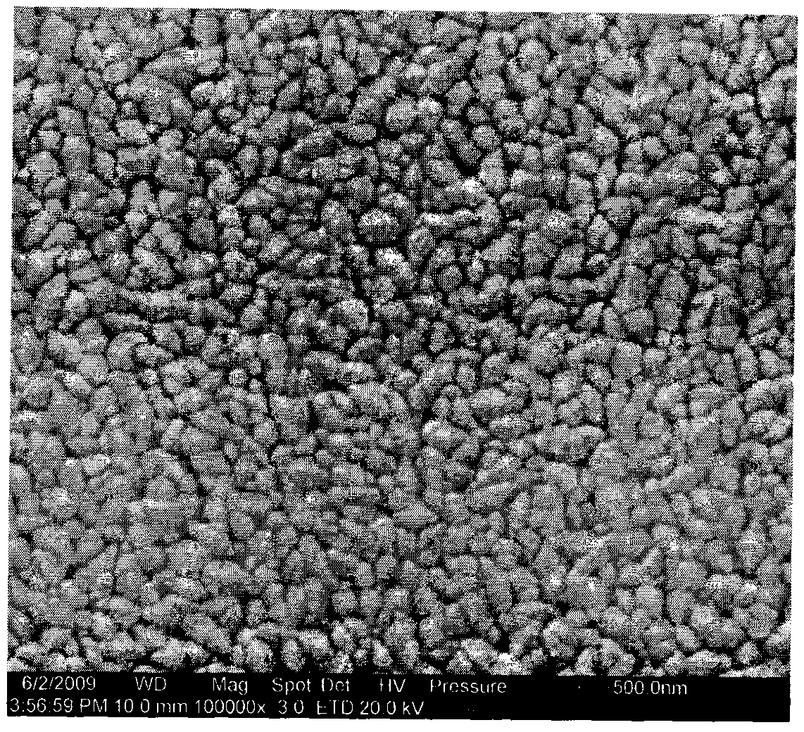
[0027] Change the distance between the target and the substrate from 40mm to 80mm, and other deposition parameters are the same as in Example 1 to obtain TiO with different diameters 2 nanorod arrays. image 3 and Figure 4 are the surface topography photos of the nanorod arrays prepared when the distance between the target substrates is 40 mm and 80 mm, respectively. According to this embodiment, it can be seen that the diameter of the nanorod increases with the shortening of the distance from the target to the substrate, thus providing a method for controlling the diameter of the nanorod.

Embodiment 3

[0028] Example 3: One of the preparation methods of titanium dioxide nanorod arrays with different morphologies

[0029] keep O 2 Air pressure is 3.1×10 -1 Pa, the sputtering current is 0.52A, the distance between the target and the substrate is 50mm, and the pressure of the sputtering pressure is changed from 1Pa to 5Pa, and TiO with different shapes and diameters will be obtained. 2 nanorod arrays. Figure 5 and Figure 6 are the surface morphology of the nanorod arrays prepared when the sputtering pressure is 5Pa and 1Pa, respectively.


PUM


Abstract

The invention relates to a preparation method for a TiO2 nanometer rod array of a dye sensitized solar cell. The TiO2 nanometer rod array of the dye sensitized solar cell is prepared by a DC reaction magnetron sputtering method. The method comprises the following steps of: putting a substrate surface into a DC reaction magnetron sputtering device and vacuumizing until the pressure is less than 1*10<3>Pa, wherein Ar gas is taken as sputtering gas and O2 gas is taken as reaction gas; and controlling the pressure of the reaction gas at 0.09 to 1P, the pressure of the sputtering gas at 1 to 5Pa, the sputtering power at 200 to 250w, and the distance from a target to the substrate at 40 to 80mm. The method prepares the TiO2 nanometer rod array by controlling the technological conditions such as the gas pressure, the substrate temperature, the sputtering power and the distance from the target to the substrate. The TiO2 nanometer rod prepared by the method has high preferred orientation along 220, and a highest photovoltaic conversion efficiency of 5.24 percent when applied to the dye sensitized solar cell.

Description

technical field [0001] The invention belongs to the field of preparation and application of dye-sensitized solar cell materials, and in particular relates to a TiO2 dye-sensitized solar cell 2 Preparation methods of nanorod arrays. Background technique [0002] In 1991, Swiss scientist Gratzel used nanoporous Ti O 2 The thin film is used as photoelectrode to prepare a new type of solar cell, which is called dye-sensitized solar cell, and the obtained efficiency reaches 7%, and now the efficiency of this cell has exceeded 11%. In recent years, nanocrystalline TiO 2 As an electrode material, it has been widely used in dye-sensitized solar cells (DSSC) devices. Energy conversion efficiency of dye-sensitized solar cells and TiO 2 The properties of the film material have a great relationship, which includes the specific surface area, porosity, light scattering performance of the film and the TiO2 that constitutes the nanocrystalline film material. 2 Crystal form, particle si...

Claims


Application Information

Patent Timeline
IPC IPC(8): H01G9/042H01G9/20H01M14/00H01L51/44H01L51/46H01L51/48C23C14/35C23C14/08
CPCY02E10/542Y02E10/549Y02P70/50
Inventor 李灿孟立建
Owner DALIAN INST OF CHEM PHYSICS CHINESE ACAD OF SCI
Learn More