Low-cost interface structure and method for monitoring direct current side information of solar cell panel

A technology for solar panels and information monitoring, applied in electrical components, single-grid parallel feeding arrangements, transmission systems, etc., can solve the problems of high transmission power, high application cost, grid noise, attenuation and signal reflection, etc., to reduce cost, the effect of avoiding bus noise interference

Inactive Publication Date: 2011-01-19
WUXI MEIKAI ENERGY TECH
View PDF7 Cites 16 Cited by
  • Summary
  • Abstract
  • Description
  • Claims
  • Application Information

AI Technical Summary

Problems solved by technology

[0003] The data on the DC side of the battery board is monitored and processed through the AC power line carrier interface. The disadvantage is that the information is isolated from the 220V AC through the power line communication module and the coupling transformer, which is easily affected by grid noise, attenuation and signal reflection. Its application The cost is high, and a separate phase-to-phase coupler is required in the three-phase power grid system, and an additional wave trap is also required in the single-phase system to improve the communication quality. In addition, there are multiple communication modules working at the same time with a large transmission power, which may also EMC problems are generated; while the DC side data is transmitted through the wireless communication module, the application cost is high and it is easily affected by signal shielding; in a high-power photovoltaic power station, the number of solar panels is huge. In order to improve the overall power generation of the system and facilitate monitoring and maintenance, Reducing the cost of a single panel monitoring communication device is significant

Method used


Image

  • Low-cost interface structure and method for monitoring direct current side information of solar cell panel
  • Low-cost interface structure and method for monitoring direct current side information of solar cell panel
  • Low-cost interface structure and method for monitoring direct current side information of solar cell panel

Examples


Embodiment Construction

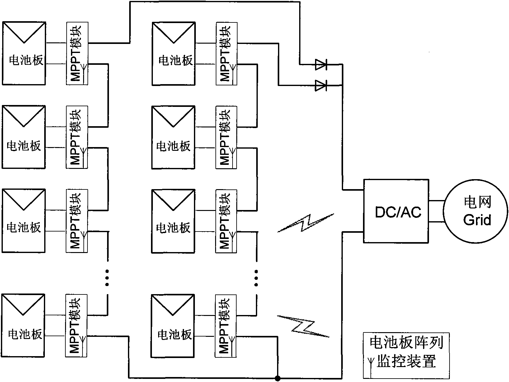
[0020] Such as image 3 As shown, the bus capacitance C of the present invention behind the BOOST circuit of the battery board monitoring communication device E Output side (high frequency loop equivalent impedance ), the design adds a low-pass filter (LPF) and a dual-capacitor coupling circuit, where the capacitor C of the low-pass filter (LPF) LPF While playing the role of low-pass filter, it is also used as an output series capacitor, and C LPF to be connected in series, since where f represents the high frequency carrier frequency (or frequency band), so Thus forming a stable high-frequency signal path; the inductance L of the low-pass filter (LPF) LPF At high frequencies, its equivalent impedance far greater than C LPF The equivalent impedance of Seen from the side of the DC bus to the BOOST circuit, it is similar to an open circuit, so the high-frequency signal path has better impedance isolation with the previous stage BOOST circuit, which enhances the stabi...


PUM


Abstract

The invention discloses a low-cost interface structure and a method for monitoring the direct current side information of a solar cell panel. The method comprises the following steps of: constructing a low pass filter and establishing a high frequency interconnected channel at the back end of a BOOST circuit booster diode so as to perform digitized carrier communication between a monitoring device and a public direct current bus which is connected with a centralized inverter or a string inverter and performing signal coupling by using double capacitors without any communication transformer orspecial communication line; and processing a mu V level communication signal by using a low transmitting power circuit and a digital phase-locking amplifier and realizing reference signal synchronization and communication frequency switching of the digital phase-locking amplifier through a bus ripple voltage and a bus average voltage so as to reduce the problems of antenna effect and electromagnetic compatibility (EMC) caused by long-distance transportation of a high frequency signal of a direct current bus and lower the cost of a solar panel monitoring communication device. The structure andthe method have good application prospects.

Description

technical field [0001] The invention relates to the technical field of information monitoring of solar panels, in particular to a low-cost interface structure and method. Background technique [0002] In solar power generation systems, especially in string systems (generally low power 1-10KW) and series parallel systems (generally 50KW-MW), the system structure is as follows figure 1 As shown, due to the differences in characteristics of different panels, differences in light radiation at different locations, shadows, dirt and damage, etc., the maximum power mismatch will be caused, resulting in a decrease in system power generation; and due to the lack of information monitoring of a single panel, it will lead to It is difficult to locate faulty or defective panels and difficult to maintain; therefore, the DC side information monitoring of a single panel is very important. In order to solve such problems, the American Enphase Company proposed in the document US20090066357 t...

Claims


Application Information

Patent Timeline
Patent Type & Authority Applications(China)
IPC IPC(8): H02J3/38H04B1/713
Inventor 牟英峰
Owner WUXI MEIKAI ENERGY TECH
Why Eureka
Try Eureka