High pressure pulse modulator and modulation method thereof for steep falling edge and low power consumption plasma immersion ion implantation

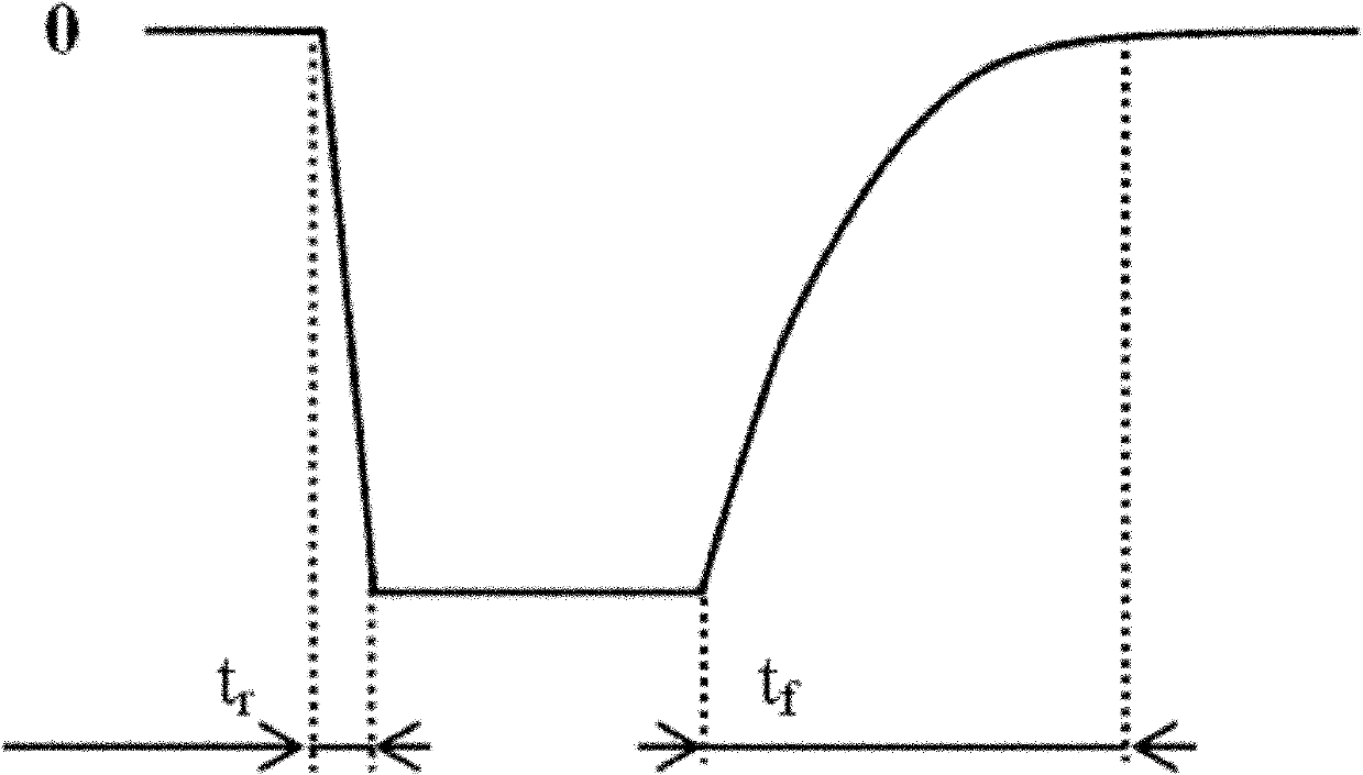
A technology of high-voltage pulse modulation and plasma immersion, applied in the direction of conversion equipment without intermediate conversion to AC, can solve the problem of long falling edge of output pulse, achieve the effect of short falling edge of waveform, improve power supply efficiency, and low cost

Active Publication Date: 2011-01-19
HARBIN INST OF TECH
View PDF2 Cites 13 Cited by
  • Summary
  • Abstract
  • Description
  • Claims
  • Application Information

AI Technical Summary

Problems solved by technology

[0005] The purpose of the present invention is to solve the problem of the long falling edge of the output pulse of the high-voltage pulse modulator for plasma immersion i

Method used


Image

  • High pressure pulse modulator and modulation method thereof for steep falling edge and low power consumption plasma immersion ion implantation
  • High pressure pulse modulator and modulation method thereof for steep falling edge and low power consumption plasma immersion ion implantation
  • High pressure pulse modulator and modulation method thereof for steep falling edge and low power consumption plasma immersion ion implantation

Examples


specific Embodiment approach 1

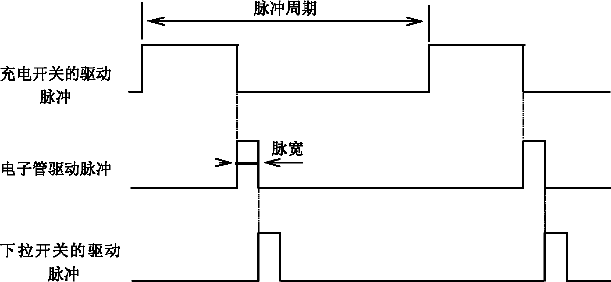
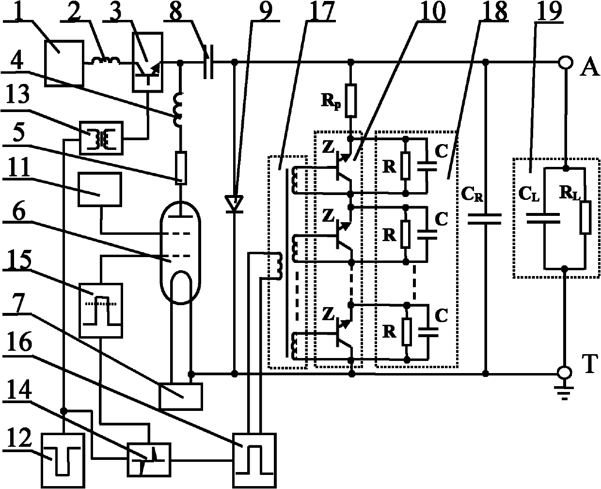
[0024] Specific implementation mode one: the following combination figure 1 , Figure 3 to Figure 5 Describe this embodiment, the high-voltage pulse modulator for plasma immersion ion implantation with steep falling edge and low power consumption described in this embodiment, which includes a DC high-voltage power supply 1, a charging current-limiting inductor 2, a charging IGBT series switch 3, and a current spike suppression inductor 4. Load current limiting resistor 5, vacuum tetrode 6, filament power supply 7, high voltage pulse capacitor 8, high voltage silicon stack 9, pull-down discharge current limiting resistor R p , pull-down IGBT series switch 10, parasitic capacitance C R , the second gate power supply 11, the driving original signal unit 12 of the charging switch, the charging synchronous isolation driving circuit 13, the pulse delay circuit 14, the electron tube driving circuit 15, the driving original signal unit 16 of the pull-down switch and the pull-down syn...

specific Embodiment approach 2

[0035] Specific implementation mode two: the following combination image 3 Describe this embodiment, the difference between this embodiment and Embodiment 1 is that it also includes a pull-down IGBT voltage equalizing circuit 18, and the pull-down IGBT voltage equalizing circuit 18 is connected in parallel between the emitter and the collector of the pull-down IGBT series switch 10 . Other components and connections are the same as those in Embodiment 1.

specific Embodiment approach 3

[0036] Specific implementation mode three: the following combination image 3 Describe this embodiment, this embodiment is the further explanation to Embodiment 2, described pull-down synchronous isolation drive circuit 17 adopts pulse transformer, and the primary coil of pulse transformer connects the output end of driving original signal unit 16 of pull-down switch, and pulse transformer has multiple secondary coils;

[0037] The pull-down IGBT series switch 10 is composed of a plurality of IGBT low-voltage switches Z connected in series,

[0038] The pull-down IGBT voltage equalizing circuit 18 is composed of a plurality of resistance-capacitance voltage divider circuits, and each resistance-capacity voltage divider circuit is composed of a voltage-dividing resistor R and a voltage-dividing capacitor C in parallel,

[0039] Each secondary coil is connected in parallel between the collector and gate of an IGBT low-voltage switch Z, and a resistance-capacitance voltage divid...


PUM

PropertyMeasurementUnit
Voltage rangeaaaaaaaaaa
Pulse widthaaaaaaaaaa

Abstract

The invention relates to a high pressure pulse modulator and a modulation method thereof for steep falling edge and low power consumption plasma immersion ion implantation, which belongs to the technical field of pulse power and solves the problem of long falling edge of the output pulse of the traditional high pressure pulse modulator for plasma immersion ion implantation. A high pressure pulse is modulated by using a vacuum electron tube as a main switch, a charging process of a high pressure impulse capacitor is controlled by using a charging IGBT (Insulated Gate Bipolar Translator) series switch, and the power consumption on a charging current-limiting resistor is eliminated. When the high pressure pulse is cut off, the drop-down IGBT series switch is switched on, charges remained in a load capacitor and a parasitic capacitor can quickly flow through a discharging current-limiting device and the drop-down IGBT series switch to be released so that the falling edge of the output high pressure pulse is greatly reduced. The invention is used for accurately controlling the high pressure pulse in a plasma immersion ion implantation process.

Description

technical field [0001] The invention relates to a high-voltage pulse modulator and a modulation method for plasma immersion ion implantation with steep falling edge and low power consumption, belonging to the technical field of pulse power. Background technique [0002] Plasma immersion ion implantation technology is an advanced surface modification technology, which has attracted widespread attention in recent years. In the process of plasma immersion ion implantation, the processed workpiece is placed in a vacuum chamber, which is excited by an external plasma source to generate plasma, and a negative pulse high voltage is applied to the processed workpiece. Due to the mass difference between electrons and ions in the plasma, the electrons The ions are quickly repelled away from the workpiece, and the ions are relatively static, so that a plasma pressure drop zone, that is, the plasma sheath zone, is formed around the workpiece. Under the acceleration of the sheath voltag...

Claims


Application Information

Patent Timeline
IPC IPC(8): H02M3/07
Inventor 田修波朱宗涛巩春志杨士勤
Owner HARBIN INST OF TECH
Why Eureka
Try Eureka