Method for machining output shaft assembly

A processing method and output shaft technology are applied in the processing field of the output shaft assembly of the automobile starter motor, which can solve the problem that the involute tooth-shaped parts cannot be machined by hobbing, so as to improve the comprehensive product quality and yield, and improve the manufacturing accuracy. and processing efficiency, the effect of improving the utilization rate of metal materials

Inactive Publication Date: 2011-01-26
NO 59 RES INST OF CHINA ORDNANCE IND
View PDF5 Cites 27 Cited by
  • Summary
  • Abstract
  • Description
  • Claims
  • Application Information

AI Technical Summary

Problems solved by technology

[0007] In order to improve the processing efficiency and the overall quality of the helical spline, and solve the problem that the involute tooth-shaped parts without undercuts cannot be machined by hobbing, the above-mentioned special processing includes the processing of the involute helical spline, and the involute helical Splines are processed by cold rolling forming technology

Method used


Image

  • Method for machining output shaft assembly
  • Method for machining output shaft assembly
  • Method for machining output shaft assembly

Examples


Embodiment 1

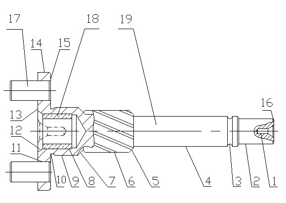
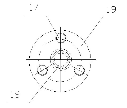
[0054] Embodiment 1, a processing method of the output shaft assembly, including the processing of the output shaft 19 and the assembly of the gear shaft 17, the oil bearing 18 and the output shaft 19, the processing flow of the output shaft 19 includes blank preparation, blank making, machining, Special processing and auxiliary processing;

[0055] Billet making includes preform and billet making by cold extrusion forming technology;

[0056] Special processing includes the processing of involute helical spline 6, and the processing of involute helical spline 6 adopts cold rolling forming technology;

[0057] The special processing also includes punching. The punching is to use the punching die disclosed in the patent application number 201020055240.9 to punch out three bottom holes of the gear shaft on the output shaft. The size error of the bottom holes of the three gear shafts is ≤0.02, and the position error of the center hole of the small end and the hole containing the...

Embodiment 2

[0062] Embodiment 2, a processing method of the output shaft assembly, including the processing of the output shaft 19 and the assembly of the gear shaft 17, the oil bearing 18 and the output shaft 19, the processing flow of the output shaft 19 includes blank preparation, blank making, machining and Special processing and auxiliary processing;

[0063] The specific operation steps of the processing of the output shaft 19 are as follows:

[0064] Billet preparation includes

[0065] (1) Cutting: The hot-rolled bar is cut by cutting or sawing;

[0066] (2) Shot blasting: remove the oxide skin on the surface of the lower material;

[0067] (3) Car billet: the collapse and chamfering formed at both ends of the material when the car is removed for blanking, which improves the process stability of the cold extrusion preform;

[0068] (4) Surface treatment: Through surface phosphating and saponification treatment, a layer of phosphating and saponification film is evenly covered on...


PUM


Abstract

The invention discloses a method for machining an output shaft assembly. The method comprises the following steps of: machining an output shaft; and assembling a gear shaft, an oil-retaining bearing and the output shaft. The process flow for machining the output shaft comprises blank preparation, blank fabrication, machining, non-traditional machining and auxiliary treatment, and is characterized in that the blank fabrication comprises blank prefabrication and blank fabrication by adopting cold extrusion forming technology. In the method, a blank is fabricated by adopting the cold extrusion forming technology; an involuting spiral spline is machined by adopting cold roll forming technology; machining is performed by adopting a computerized numerical control (CNC) lathe; punching and assembly are performed by adopting a special punching die and a riveting extrusion assembly die; and specific machining steps and method are adopted. Therefore, the fabricating precision and the machining efficiency of the output shaft assembly are improved; the comprehensive quality and the yield of products are improved; raw material and energy consumption is reduced; and environmental protection is reduced.

Description

technical field [0001] The invention relates to a processing method of an output shaft assembly, in particular to a processing method of an output shaft assembly of an automobile starter motor. Background technique [0002] At present, the most widely used starter motor in the automotive industry is the reduction transmission starter motor, and the planetary gear reduction transmission starter motor accounts for the largest proportion. Its application in cars reaches 70-80%, and its application in the entire automotive industry reaches More than 60%. [0003] The output shaft assembly of the automobile starter motor is one of the most important parts of the planetary gear reduction transmission type starter motor. The quality and precision of its processing directly determine the assembly, transmission, vibration, noise, durability, and Starting and many other key performances. [0004] figure 1 A typical automotive starter motor output shaft assembly is shown. The o...

Claims


Application Information

Patent Timeline
Patent Type & Authority Applications(China)
IPC IPC(8): B23P15/00
Inventor 韩济才车路长彭树杰熊德龙张焕莲
Owner NO 59 RES INST OF CHINA ORDNANCE IND
Why Eureka
Try Eureka