Energy-storage type refrigeration method and refrigeration system

A refrigeration system and constant temperature system technology, which is applied in household refrigeration devices, lighting and heating equipment, household appliances, etc., can solve the problems of small cooling range, power consumption, and high operating costs, and achieve large cooling range, convenient operation and use, and refrigeration. A large amount of effect

Inactive Publication Date: 2011-01-26
李蒙初 +1
View PDF5 Cites 2 Cited by
  • Summary
  • Abstract
  • Description
  • Claims
  • Application Information

AI Technical Summary

Problems solved by technology

Among the refrigeration media used in heat pump cooling air conditioners: carbon-fluoride is an ozone killer, the price of lithium bromide is high, and liquid ammonia is a highly toxic compound; heat pump cooling air conditioners have high manufacturing costs, slow cooling, small cooling range, high operating costs, and consume a lot of electricity , not conducive to environmental protection

Method used


Image

  • Energy-storage type refrigeration method and refrigeration system
  • Energy-storage type refrigeration method and refrigeration system
  • Energy-storage type refrigeration method and refrigeration system

Examples


Embodiment 1

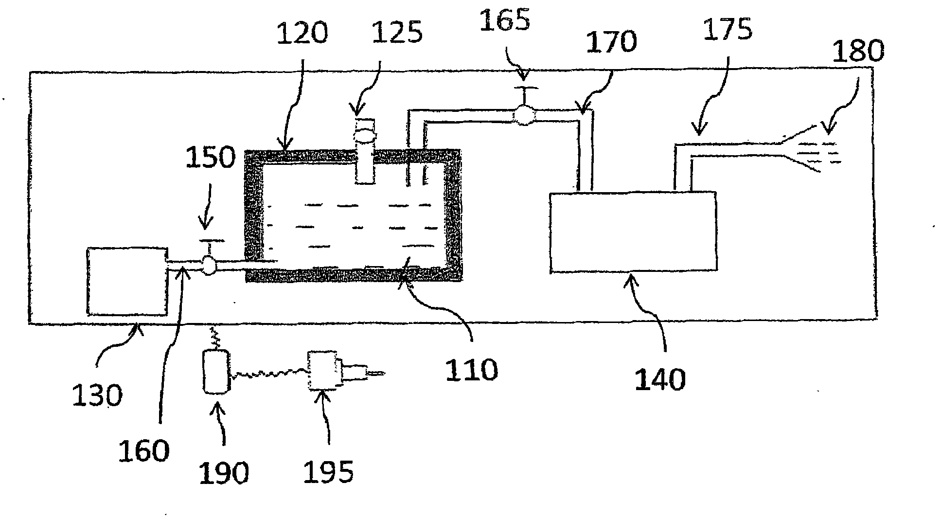
[0061] Embodiment 1: see attached figure 1 .

[0062] An air supply (blowing), air extraction (extraction) refrigeration system, comprising:

[0063] An insulated container 120 that has the ability to contain low-temperature liquid air and can ensure that the liquid air remains in a liquid state,

[0064] Liquid air 110 is contained in a thermal insulation container 120,

[0065] A liquid air input pipeline that communicates with the heat preservation container 120 and is equipped with a valve 125,

[0066] A blower blower fan 130 (i.e. air delivery device), this blower fan 130 is connected with the bottom of the heat preservation container 120 by the airflow duct 160 that valve 150 is installed, is used for sending gaseous air in the heat preservation container 120, to impel cold air from heat preservation The container 120 flows to the cold air outlet 180,

[0067] A cold air outlet 180,

[0068] One end communicates with the top of the heat preservation container 120 a...

Embodiment 2

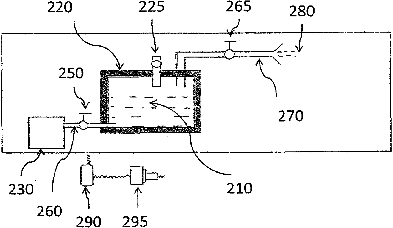
[0075] Embodiment 2: see attached figure 2 .

[0076] A blower refrigeration system, comprising:

[0077] An insulated container 220 that has the ability to contain low-temperature liquid air and can ensure that the liquid air remains in a liquid state,

[0078] Liquid air 210 is contained in a thermal insulation container 220,

[0079] One is communicated with the heat preservation container 220, the liquid air input pipeline that valve 225 is installed,

[0080] A cold air outlet 280,

[0081] One is communicated with insulated container 220 with cold wind outlet 280, and the air outlet pipeline 270 that valve 265 is installed, so that cold air flows to cold air outlet 280 from the insulated container 220,

[0082] A blower blower fan 230 (i.e. air delivery device), this blower fan 230 is connected with the bottom of the heat preservation container 220 by the inlet flow pipe 260 that valve 250 is installed, and gaseous air is sent in the heat preservation container 220,...

Embodiment 3

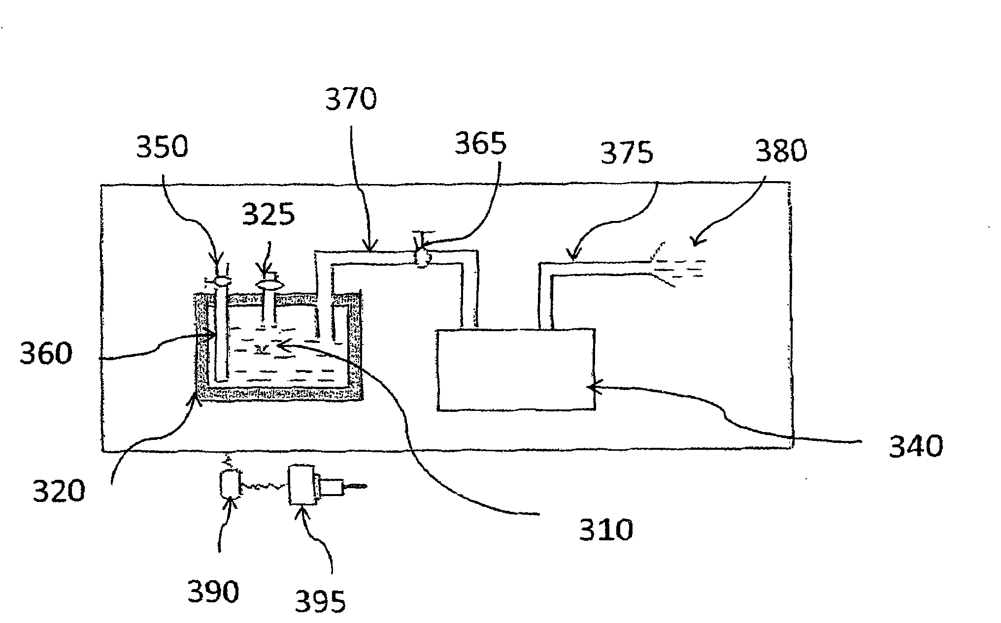
[0088] Embodiment 3: see attached image 3 .

[0089] A draft refrigeration system comprising:

[0090] An insulated container 320 that has the ability to contain low-temperature liquid air and can ensure that the liquid air remains in a liquid state,

[0091] Liquid air 310 is contained in a thermal insulation container 320,

[0092] A liquid air input pipeline that communicates with the heat preservation container 320 and is equipped with a valve 325,

[0093] An air input pipeline 360 ​​communicating with the heat preservation container 320, equipped with a valve 350 and ventilated to the atmosphere,

[0094] A cold air outlet 380,

[0095] One end communicates with the top of the insulated container 320, and an air outlet pipeline 370 with a valve 365 is installed, so that cold air flows out from the insulated container 320,

[0096] A suction fan 340 (i.e. an air extractor), the air inlet of the fan 340 is communicated with the other end of the air outlet duct 370, a...


PUM


Abstract

The invention relates to a refrigeration system which is characterized by comprising liquid air, a heat preservation container which is capable of containing low temperature liquid air and guaranteeing the state of the liquid air, a liquid air inlet pipeline which is communicated with the heat preservation container, and is provided with a valve, a cold air outlet, an air outlet pipeline which is provided with a valve and connects the heat preservation container to the cold air outlet, and an air blower which is communicated with the bottom of the heat preservation container through an air inlet pipeline which is provided with an inlet valve. When in use, the liquid air is injected into the heat preservation container, the valve in the air outlet pipeline is opened, the air blower is started, the inlet valve is opened, and then cold air is blown out from the cold air outlet through the air outlet pipeline, thereby the temperature of an air conditioner is reduced. The refrigeration system has the advantages of low manufacturing cost, high efficiency, energy conservation, instantaneous temperature reduction, large temperature reduction range, large refrigeration capacity, low noise, environmental protection, low operation cost and strong practicability.

Description

technical field [0001] The invention belongs to a refrigeration method, refrigeration equipment or system, and relates to an energy storage type refrigeration method and a refrigeration system. Background technique [0002] In the prior art, most refrigeration equipment or systems use heat pump cooling air conditioners. Heat pump air conditioners are usually composed of compressors, condensers, expansion mechanisms and evaporators. Compressed to the condenser, the heat is discharged and re-condensed into a liquid state, and flows into the evaporator through the expansion mechanism to complete a new round of cooling and cooling process. Using a heat pump cooling air conditioner, increasing the cooling capacity will inevitably increase the various parts of the system, so that the cost of the air conditioning system will increase almost proportional to the cooling capacity, and the power consumption will also increase proportionally. Among the refrigeration media used in heat...

Claims


Application Information

Patent Timeline
Patent Type & Authority Applications(China)
IPC IPC(8): F25D3/10F25D29/00
Inventor 李蒙初李广舜
Owner 李蒙初
Why Eureka
Try Eureka