Near-end machine and far-end machine of frequency shift repeater

A repeater, near-end machine technology, applied in electrical components, wireless communications, radio relay systems, etc., can solve the problems of long investment recovery time, weak wave diffraction ability, wireless propagation path loss, etc., to achieve good technology and return on investment, enhance coverage, reduce investment costs

Inactive Publication Date: 2011-01-26
SHANGHAI DETONG ENERGY & ENVIRONMENTAL PROTECTION TECH
View PDF0 Cites 5 Cited by
  • Summary
  • Abstract
  • Description
  • Claims
  • Application Information

AI Technical Summary

Problems solved by technology

[0006] However, the frequency shifting repeater converts the intermediate frequency signal introduced from the base station into a high frequency signal and then transmits it. On the one hand, it can avoid the current frequency used by the mobile communication network, but on the other hand, due to the signal frequency The higher the value, the shorter the wavelength. According to the wave diffraction experiment, the shorter the wavelength, the less obvious the wave diffraction is, that is to say, the weaker the wave diffraction ability is, the easier it is to be affected by the environment.
[0007] Especially in rural areas, restricted by geographical and economic conditions, the communication conditions in mountainous areas and rural areas are even worse. If the original repeater method or general frequency shift method is used for network construction in rural areas, the initial investment cost will be too high , causing the investment recovery time to be longer, or even impossible to recover
And because remote rural areas are far away from towns and cities, they cannot receive base station signals from cities and towns. If the original frequency 900M, 1.5G or 1.8G signals are used, the signal will be affected by the external environment, and the wireless propagation path loss will be large. There are many mountains, and the signal is easily blocked. Therefore, there is an urgent need for a system that is less affected by the external environment and has better diffraction for coverage to achieve large-area coverage in rural areas.

Method used


Image

  • Near-end machine and far-end machine of frequency shift repeater
  • Near-end machine and far-end machine of frequency shift repeater
  • Near-end machine and far-end machine of frequency shift repeater

Examples


Embodiment Construction

[0017] The technical solution of the present invention will be described in detail below according to the drawings and embodiments.

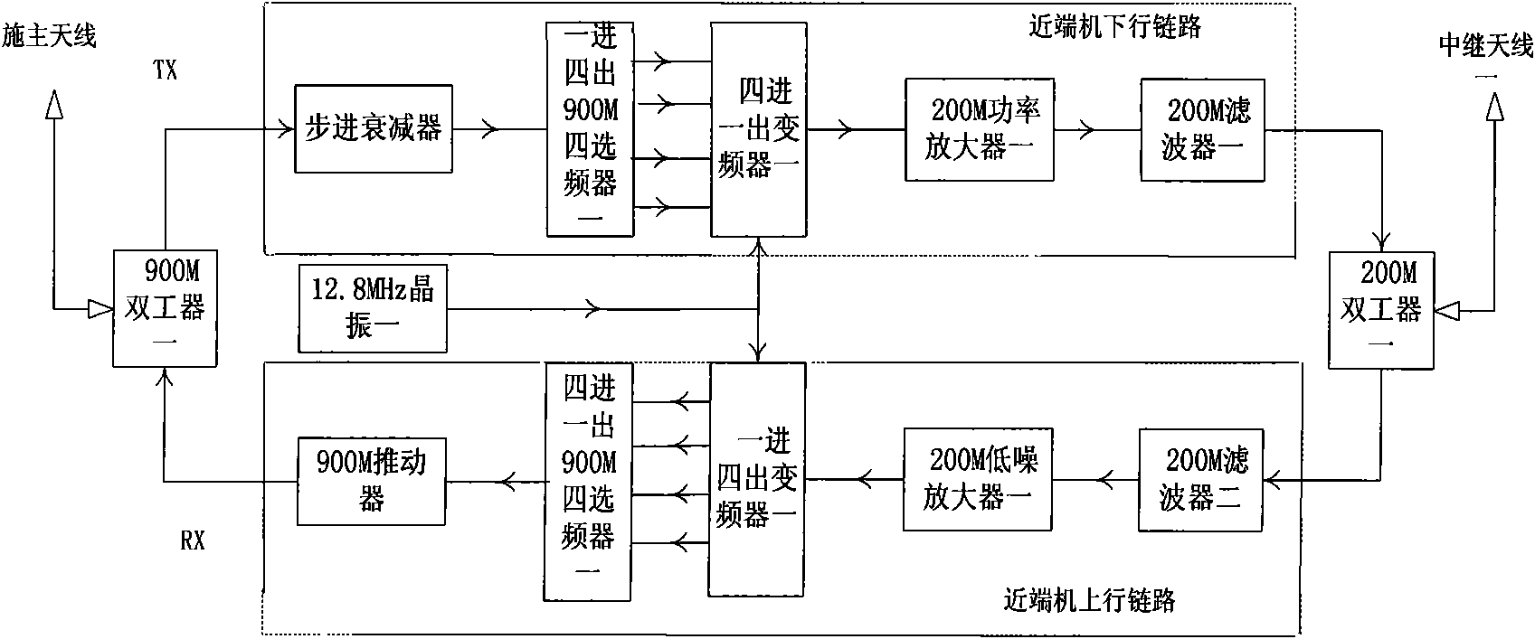
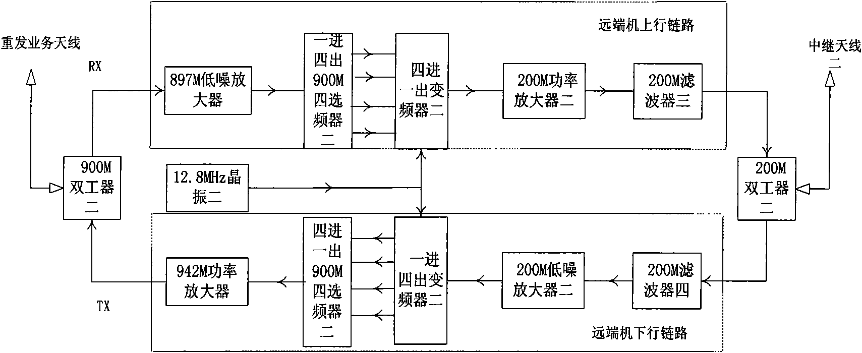
[0018] like figure 1 and figure 2 As shown, the system composition can be as follows:

[0019] 1) The near-end unit, the main part of the work of the near-end unit of the repeater, provides the functions of signal filtering, frequency shifting, amplification and control.

[0020] 2) The remote unit, the main part of the work of the remote unit of the repeater, is to provide the functions of filtering the relay frequency signal amplified by the near-end unit, and then shifting the frequency to the required frequency signal for amplification and control, so as to realize the coverage Area coverage.

[0021] 3) The relay antenna is a directional antenna facing the near-end machine (remote machine), and has the function of receiving and transmitting frequency-shifted signals.

[0022] 4) Donor antenna, a directional antenna facing the direction...


PUM


Abstract

The invention relates to a near-end machine and a far-end machine of a radio signal-covered and digital frequency shift companding-covered repeater system. The near-end machine and the far-end machine comprise a 200M power amplifier 1, a 200M filter 1, a 200M low-noise amplifier 1, a 200M filter 2 and a 200M duplexer 1, wherein a donor antenna reaches a relay antenna 1 through a 900M duplexer 1, a step attenuator, a one-way-in-and-four-way-out 900M frequency selector 1, a four-way-in-and-one-way-out frequency converter 1, the 200M power amplifier 1, the 200M filter 1 and the 200M duplexer 1 so as to form a radio signal on a downlink of the near-end machine. The technical scheme of the invention enhances signal diffraction capability, adapts to the environmental characteristics of regions such as low-telephone traffic regions of villages and suburbs, forest zones, prairies, massifs and the like well and enhances the covering capability of a system.

Description

technical field [0001] The invention relates to the technical field of wireless mobile communication, in particular to a near-end machine and a far-end machine of a digital frequency-shift companding coverage repeater covered by wireless signals. Background technique [0002] The signal coverage system repeater or repeater used in the mobile communication system belongs to the same-frequency amplification device, which refers to a radio transmission transfer device that enhances the signal during wireless communication transmission. The basic function of the repeater is an RF signal power booster. In the downlink of the repeater, the signal is picked up from the existing coverage area of ​​the donor antenna, and the signal outside the band pass is excellently isolated through the band pass filter, and the filtered signal is amplified by the power amplifier and then transmitted to the standby coverage area. In the uplink path, the signal of the mobile phone in the coverage ...

Claims


Application Information

Patent Timeline
Patent Type & Authority Applications(China)
IPC IPC(8): H04W88/08H04B7/14
Inventor 陈伟方紫娟白光辉刘明应
Owner SHANGHAI DETONG ENERGY & ENVIRONMENTAL PROTECTION TECH
Why Eureka
Try Eureka