Defect detection and response

A defect, infrared camera technology, applied in the field of photovoltaic cells

Inactive Publication Date: 2011-01-26
KLA TENCOR TECH CORP
View PDF3 Cites 39 Cited by
  • Summary
  • Abstract
  • Description
  • Claims
  • Application Information

AI Technical Summary

Problems solved by technology

This overhead in conventional lock-in thermography bec...

Method used


Image

  • Defect detection and response
  • Defect detection and response
  • Defect detection and response

Examples


Embodiment Construction

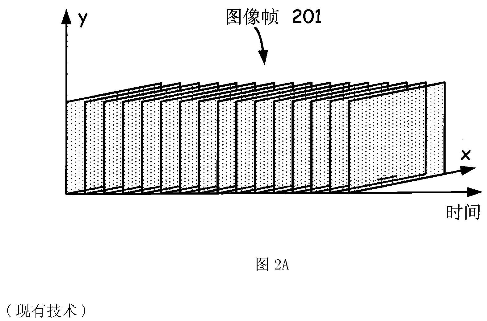
[0034] Traditional lock-in thermography requires the specimen to remain stationary while the infrared camera acquires the required number of images for lock-in integration. After one set of images has been acquired for one location on the sample, the sample is repositioned to acquire infrared images for a completely different location. This quiescent and repositioning time significantly reduces inspection throughput.

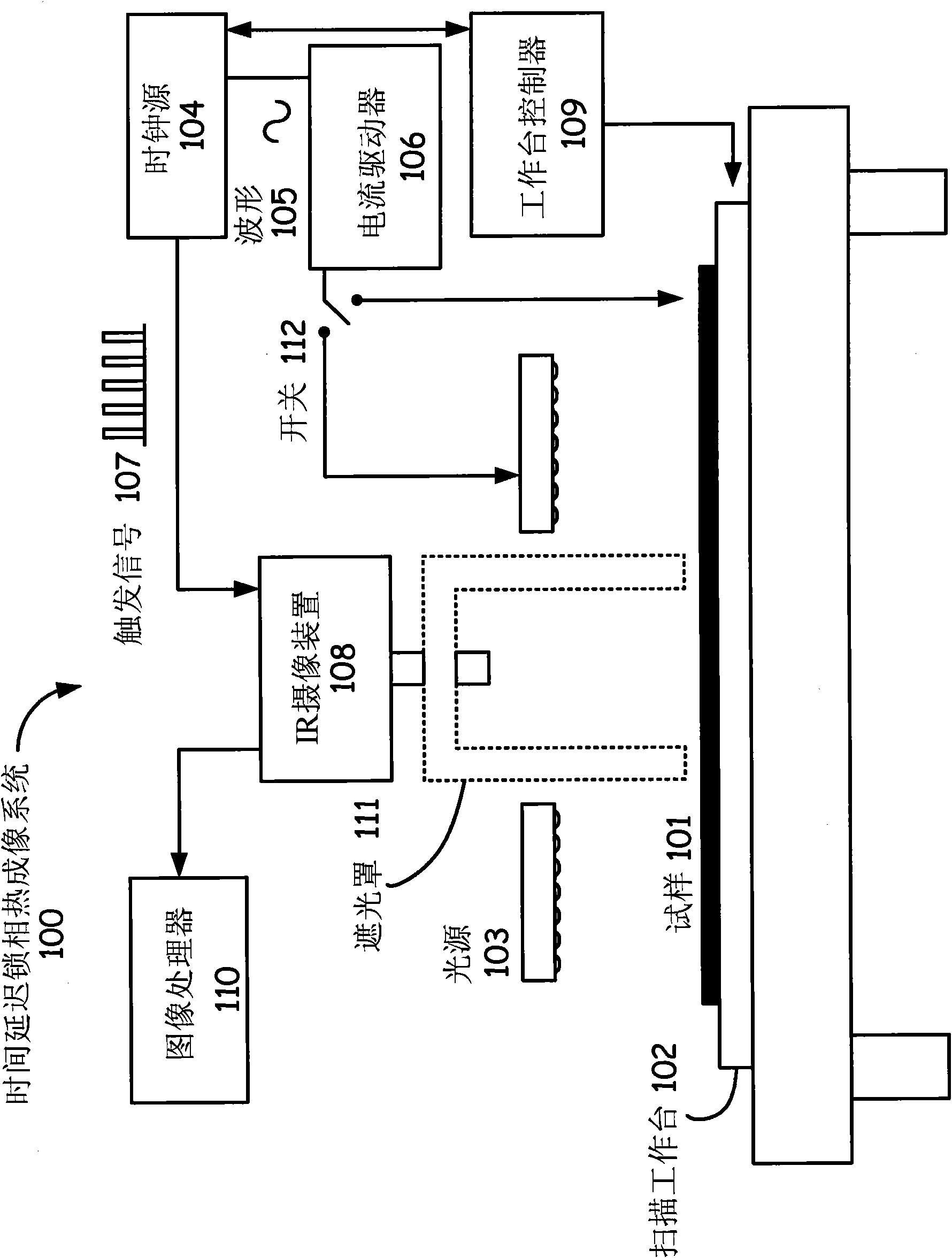
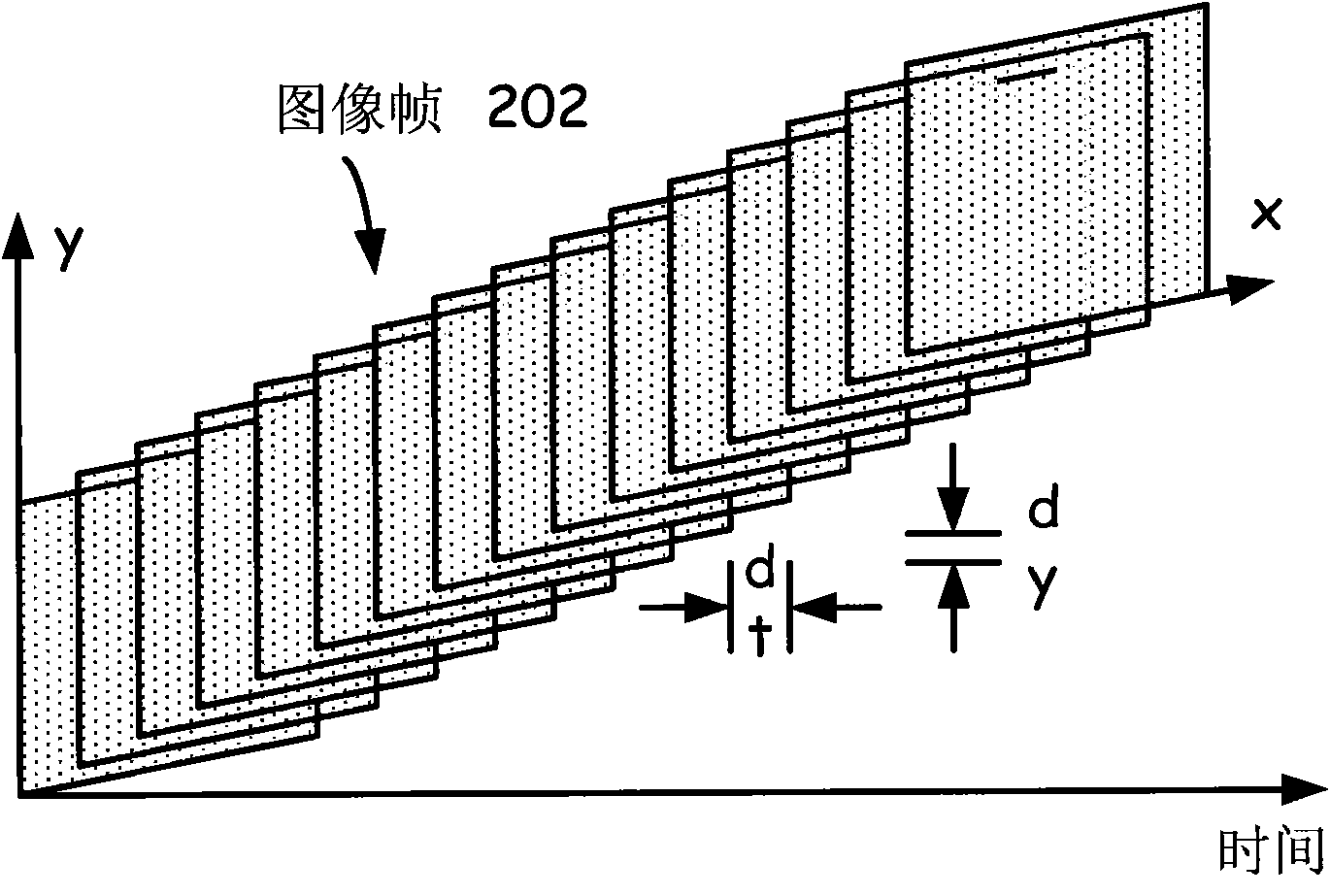
[0035] figure 1 Illustrated is an exemplary time-delay lock-in thermography system 100 that can significantly increase inspection throughput. In such an embodiment, sample 101 is placed on x-y scanning stage 102 . Applying modulation to a sample can be accomplished optically (eg, by using a modulated illumination source) or electronically (eg, by directly applying electrical current modulation to the sample). In one embodiment, switch 112 may be used to selectively connect current driver 106 to light source 103 or directly to sample 101 . In other embodiment...


PUM


Abstract

To increase inspection throughput, the field of view of an infrared camera can be moved over the sample at a constant velocity. Throughout this moving, a modulation can be provided to the sample and infrared images can be captured using the infrared camera. Moving the field of view, providing the modulation, and capturing the infrared images can be synchronized. The infrared images can be filtered to generate the time delay lock-in thermography, thereby providing defect identification. This filtering can account for the number of pixels of the infrared camera in a scanning direction. For the case of optical modulation, a dark field region can be provided for the field of view throughout the moving, thereby providing an improved signal-to-noise ratio during filtering. Localized defects can be repaired by a laser integrated into the detection system or marked by ink for later repair in the production line.

Description

technical field [0001] This application is a continuation-in-part of prior pending US Patent Application Serial No. 12 / 026,539, filed February 5, 2008. The invention relates to the field of photovoltaic cells. More specifically, the present invention relates to in-line inspection and repair of photovoltaic films. Background technique [0002] During the manufacturing process, the coupons may develop localized electrical defects that cause current leakage. Exemplary coupons may include optoelectronic materials (eg, 156mm x 156mm wafers or 2160mm x 2460mm substrates or continuous webs), semiconductor wafers, or printed circuit boards. Electrical defects (eg, shunts or localized weak diodes) leak current and thus can reduce the performance of the coupon or even compromise the functionality of the devices on the coupon. Therefore, it is highly desirable to accurately detect the location of such electrical defects. [0003] The defects cause high current densities to continue...

Claims


Application Information

Patent Timeline
IPC IPC(8): H01L21/66H01L31/042
CPCG02F1/1309G06T7/001G01N25/72G06T2207/10048G06T2207/30148
Inventor G·赵G·H·扎帕拉克S·S·H·恩盖M·维茨-依拉凡尼A·利维V·达玛蒂卡利
Owner KLA TENCOR TECH CORP
Why Eureka
Try Eureka