Crankcase ventilation device of cylinder cover one-piece engine

A technology of crankcase ventilation and cylinder head cover, which is applied in the direction of crankcase ventilation, engine components, machines/engines, etc., and can solve problems such as increasing air pollution

Active Publication Date: 2011-03-09
东风朝阳朝柴动力有限公司
View PDF5 Cites 7 Cited by
  • Summary
  • Abstract
  • Description
  • Claims
  • Application Information

AI Technical Summary

Problems solved by technology

In addition, because the combustible mixture and exhaust gas escape into the crankcase, the pressure in the crankcase will increase, and the engine oil will seep from the crankshaft oil seal, crankcase gasket, etc., and the high-temperature oil vapor will increase the damage to the engine. increase air pollution

Method used


Image

  • Crankcase ventilation device of cylinder cover one-piece engine
  • Crankcase ventilation device of cylinder cover one-piece engine
  • Crankcase ventilation device of cylinder cover one-piece engine

Examples


Embodiment Construction

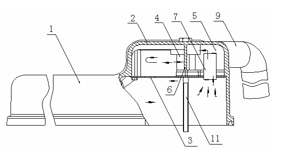
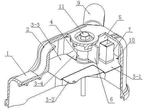
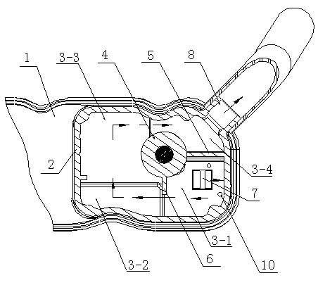
[0010] The structural principles of the present invention will be described in more detail below through embodiments in conjunction with the accompanying drawings. The cylinder head cover integrated engine crankcase ventilation device has a specific structural scheme: the rear end of the cylinder head cover 1 is provided with an oil and gas condensation chamber 2, and the condensation chamber is a single-layer structure. There is a bolt support 4 between the oil-gas condensation chamber 2 and the baffle plate 3, the fully enclosed partition plate 5 and the semi-closed partition plate 6 are vertically arranged with the bolt support 4 as their respective endpoints, and the baffle plate 3 is used as the bolt support 4 and the fully enclosed partition The bottom plate of board 5 (as figure 1 , figure 2 ). The breathing tube 7 is installed on the baffle plate 3 as the oil gas inlet of the crankcase, and the fully enclosed partition plate 5 isolates the breathing tube 7 from the ...


PUM


Abstract

The invention discloses a crankcase ventilation device of cylinder cover one-piece engine. The rear end of the cylinder cover is provided with an oil-gas condensation chamber. A bolt pillar is arranged between the oil-gas condensation chamber and a baffle plate. A totally-enclosed partition plate and a semi-enclosed partition plate are arranged vertically taking the bolt pillar as respective end points. The baffle plate is used as a bottom plate of the bolt pillar and the totally-enclosed partition plate. A breathing tube is mounted on the baffle plate and used as an oil-gas inlet of the crankcase. The totally-enclosed partition plate isolates the breathing tube from an outlet channel of a breathing apparatus. Gaps are remained respectively between the lower end and the side end of the semi-enclosed partition plate and the baffle plate and between the lower end and the side end of the semi-enclosed partition plate and the inner wall of the condensation chamber. The goal of oil and gas separation is achieved in a way that the oil mist within the crankcase of the engine rises to the top of the engine under the action of differential pressure between the crankcase and the outside, is inhaled by the breathing tube into the condensation chamber, flows to the baffle plate after being condensed on the walls of the chamber body, then flows clockwise within the chamber around the bolt pillar, finally flows back to a rocker chamber of the engine cylinder cover through an oil returning opening arranged in a first region of the baffle plate.

Description

technical field [0001] The invention belongs to engine components, in particular to a device for separating and ventilating oil and gas in the crankcase of the engine. Background technique [0002] During the working process of the diesel engine, there is always a part of the mixed gas of air, diesel oil and engine oil (including the exhaust gas discharged from the cylinder) into the crankcase through the piston ring. After the mixed gas condenses in the crankcase, it will make the lubricating oil thinner and Change the physical parameters of the lubricating oil. What's more serious is that the exhaust gas contains water vapor and sulfur dioxide, and the water vapor condenses in the engine oil to form foam, which destroys the oil supply. This phenomenon is especially serious in winter. Sulfur dioxide meets water to form sulfurous acid, and sulfurous acid meets oxygen in the air to form sulfuric acid. The appearance of these acidic substances not only deteriorates the engine...

Claims


Application Information

Patent Timeline
Patent Type & Authority Applications(China)
IPC IPC(8): F01M13/04F02F7/00
Inventor 苑朝晖曹晓峰张宏辉逯明张永胜汪自强臧真伟霍俊兰张旭东李晓刚李文才胡凤杰
Owner 东风朝阳朝柴动力有限公司
Why Eureka
Try Eureka