Coal decomposing equipment

A material and equipment technology, applied in the field of coal decomposition equipment, can solve the problems of low added value, inability to be heated uniformly, decomposition, pollution, etc., to achieve the effect of saving and utilizing energy, improving utilization rate and utilization level

Inactive Publication Date: 2011-03-16
HENAN DRAGON INTO COAL TECH CO LTD
View PDF6 Cites 28 Cited by
  • Summary
  • Abstract
  • Description
  • Claims
  • Application Information

AI Technical Summary

Problems solved by technology

[0005] At present, there are mainly two types of commonly used coal decomposition equipment. One is the shaft kiln structure, which burns flue gas and combustible gas produced by coal, which makes the combustible gas have low purity and low added value, and some of it is discharged, causing A lot of waste of resources and pollution of the environment
Another type of vertical kiln is that the coal blocks are placed on a partition with holes, and there is a heater above the coal block. Because the coal blocks on the partition have a certain accumulation thickness, they cannot be heated and decomposed evenly, and the decomposed gas needs to be used to Circular heating, decomposition, and more importantly, because of the existence of a large number of circulation vent holes on the coal separator, coal powder will leak from the vent holes, so when coal powder needs to enter the shaft kiln, it needs to be processed into coal lumps first, Therefore, pulverized coal cannot be directly used for kiln body separation, which correspondingly increases the cost of pulverized coal decomposition and reduces economic benefits

Method used


Image

  • Coal decomposing equipment
  • Coal decomposing equipment
  • Coal decomposing equipment

Examples


Embodiment 1

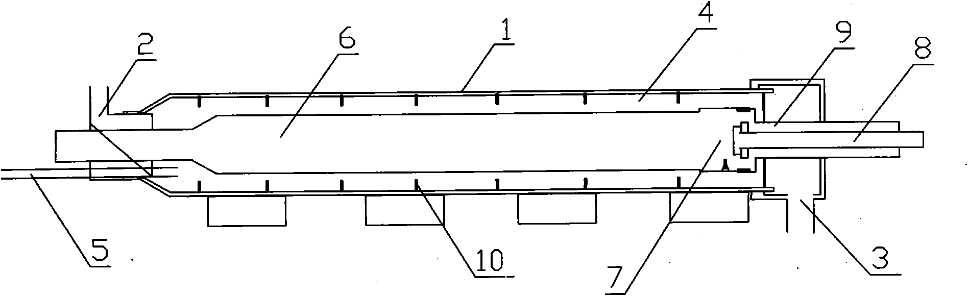
[0023] Such as figure 1 Shown: a kind of coal material decomposition equipment, including a closed kiln body 1 with a material inlet 2 and a material outlet 3, the kiln body 1 is a horizontal kiln, a rotary kiln body, and a flame gas is set inside the kiln body 1 The pipeline heating mechanism, the coal substance propelling decomposition channel 4 formed between the flame gas pipeline heating mechanism and the inner wall of the kiln body 1, the coal decomposition gas collection pipe 5 communicating with the coal substance propelling decomposition channel 4 is arranged on the kiln body 1, A push plate 10 is arranged on the inner wall of the kiln. The flame pipeline heating mechanism includes a flame heat dissipation pipe 6 and a combustion chamber 7 , and the combustion chamber 7 communicates with a fuel supply pipe 8 and an air supply pipe 9 arranged outside the kiln body 1 . The fuel in the fuel supply pipe 8 and the air in the air supply pipe 9 are mixed and burned in the c...

Embodiment 2

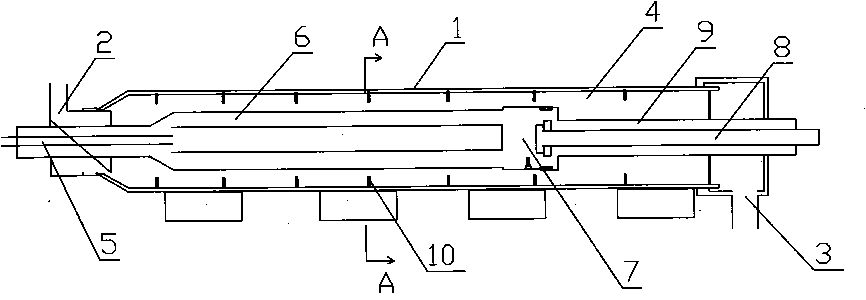
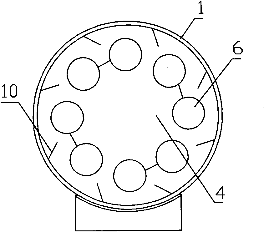
[0025] Such as figure 2 , image 3 Shown: a kind of coal material decomposition equipment, including a closed kiln body 1 with a material inlet 2 and a material outlet 3, the kiln body 1 is a horizontal kiln, a rotary kiln body, and a flame gas is set inside the kiln body 1 The pipeline heating mechanism, the coal substance propelling decomposition channel 4 formed between the flame gas pipeline heating mechanism and the inner wall of the kiln body 1, the coal decomposition gas collection pipe 5 communicating with the coal substance propelling decomposition channel 4 is arranged on the kiln body 1, A push plate 10 is arranged on the inner wall of the kiln. The flame pipeline heating mechanism includes a flame heat dissipation pipe 6, a combustion chamber 7, and a fuel supply pipe 8 and an air supply pipe 9 in communication. The flame heat dissipation pipe is a plurality of parallel close-packed pipes or tube-like close-packed pipes, which can transfer the generated heat to ...

Embodiment 3

[0027] Such as Figure 4 Shown: a kind of coal material decomposition equipment, including a closed kiln body 1 with a material inlet 2 and a material outlet 3, the kiln body 1 is a vertical kiln, the kiln body 1 is provided with a flame gas pipeline heating mechanism, The coal substance propelling decomposition channel 4 formed between the flame gas pipeline heating mechanism and the inner wall of the kiln body 1, the coal decomposition gas collection pipe 5 communicating with the coal substance propelling decomposition channel 4 is arranged on the kiln body 1, and the kiln body wall is provided Push plate 10. The flame pipeline heating mechanism includes a flame heat dissipation pipe 6 , and the flame heat dissipation pipe 6 is connected with a combustion chamber 7 , a fuel supply pipe 8 and an air supply pipe 9 arranged outside the kiln body 1 . The flame heat dissipation pipe is a plurality of parallel close-packed pipes or tube-like close-packed pipes, which can transfer...


PUM


Abstract

The invention discloses coal decomposing equipment, comprising a sealed kiln body with a feeding hole and a discharge hole, wherein the kiln body is provided with a flame gas pipe heating mechanism; coal propelling and decomposing channels are formed between the flame gas pipe heating mechanism and the inner wall of the kiln body; and a coal decomposed gas collecting pipe communicated with the coal propelling and decomposing channels is arranged on the kiln body. As the equipment conducts and radiates vast heat generated by the flame gas pipe heating mechanism on the coal dust in the coal propelling and decomposing channels, the coal dust fully absorbs the heat and is heated and decomposed into gases, tar gases and coal with higher heat value in the coal propelling and decomposing channels, the gases and tar gases are connected with a gas dedusting and liquefying mechanism outside the rotary kiln by the coal decomposed gas collecting pipe, and the gases and tar gases obtained through decomposition are collected, dedusted, separated and liquefied under pressure.

Description

technical field [0001] The invention belongs to the technical field of comprehensive utilization of coal substances, energy saving and emission reduction, and in particular relates to a decomposition equipment of coal substances. Background technique [0002] Among the known technologies, there are those that use coal to produce gas, some that use coal to produce natural gas, and those that use coal for high-temperature, medium-temperature, and low-temperature coking and gas production. Screening block materials will increase the cost of raw materials, or the calorific value of the produced gas is not high, the added value is not large, and the economic and social benefits are not significant. The heating method of the furnace can be divided into external heating type, internal heating type and internal heating and external heating mixed type. The heating medium of the external heating furnace is not in direct contact with the raw materials, and the heat is introduced from ...

Claims


Application Information

Patent Timeline
Patent Type & Authority Applications(China)
IPC IPC(8): C10B53/04C10B21/10C10B47/00
CPCC10B53/04C10B47/30C10B47/32C10K1/04C10K1/02C10B23/00C10B57/08C10B7/00
Inventor 朱书成王希彬黄祥云曹国超刘伟李明德李晓阳
Owner HENAN DRAGON INTO COAL TECH CO LTD
Why Eureka
Try Eureka