Method and device for processing revolving parts by high-speed jet injection electroforming
A high-speed jet and processing device technology, applied in the direction of electroforming, electrolysis process, etc., to overcome the long processing time, improve the quality of electroforming, and the effect of grain refinement
- Summary
- Abstract
- Description
- Claims
- Application Information
AI Technical Summary
Problems solved by technology
Method used
Image
Examples
Embodiment 1
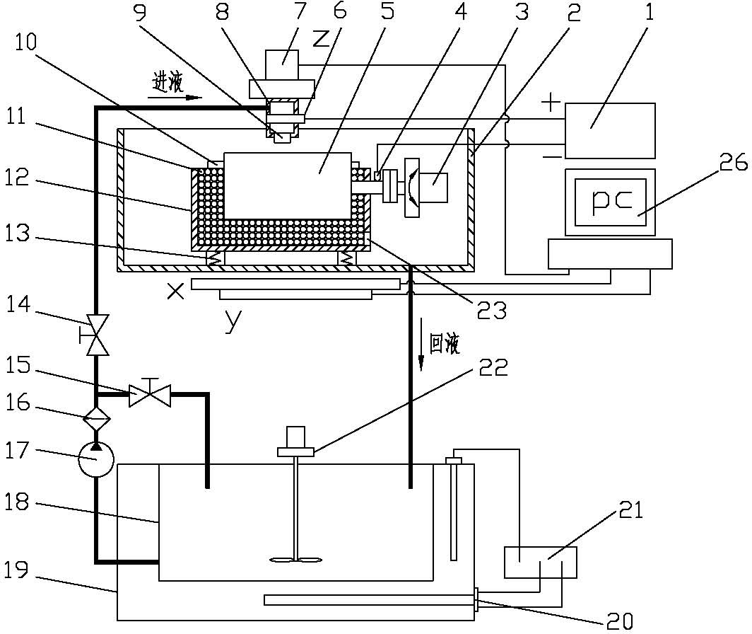
[0038] Such as figure 1 Shown.
[0039] A high-speed jet injection electroforming method for rotating parts, which includes the following steps:
[0040] (1) First, connect the electroforming core mold to a rotating drive device and at the same time connect to the power cathode to form a deposition cathode and keep the deposition cathode in a rotating state during the entire electroforming process;
[0041] (2) Half-buried the deposited cathode in the abrasive grains of the electroforming tank (the abrasive grains should be ceramic balls, glass balls or metal abrasive grains with a density greater than the electroforming layer) or make it interact with a friction piece (natural jade or Agate stone) sliding contact on the surface;
[0042] (3) Connect the electroforming liquid nozzle (which can be a circular, narrow slot or array nozzle) and the electroforming tank with a three-dimensional motion control device, so that the electroforming liquid nozzle can move vertically and horizonta...
Embodiment 2
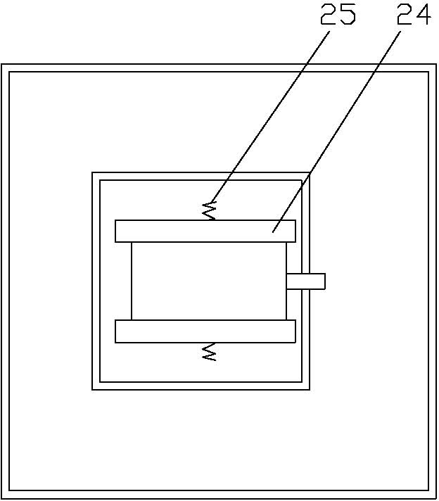
[0054] Such as Figure 1-3 Shown.
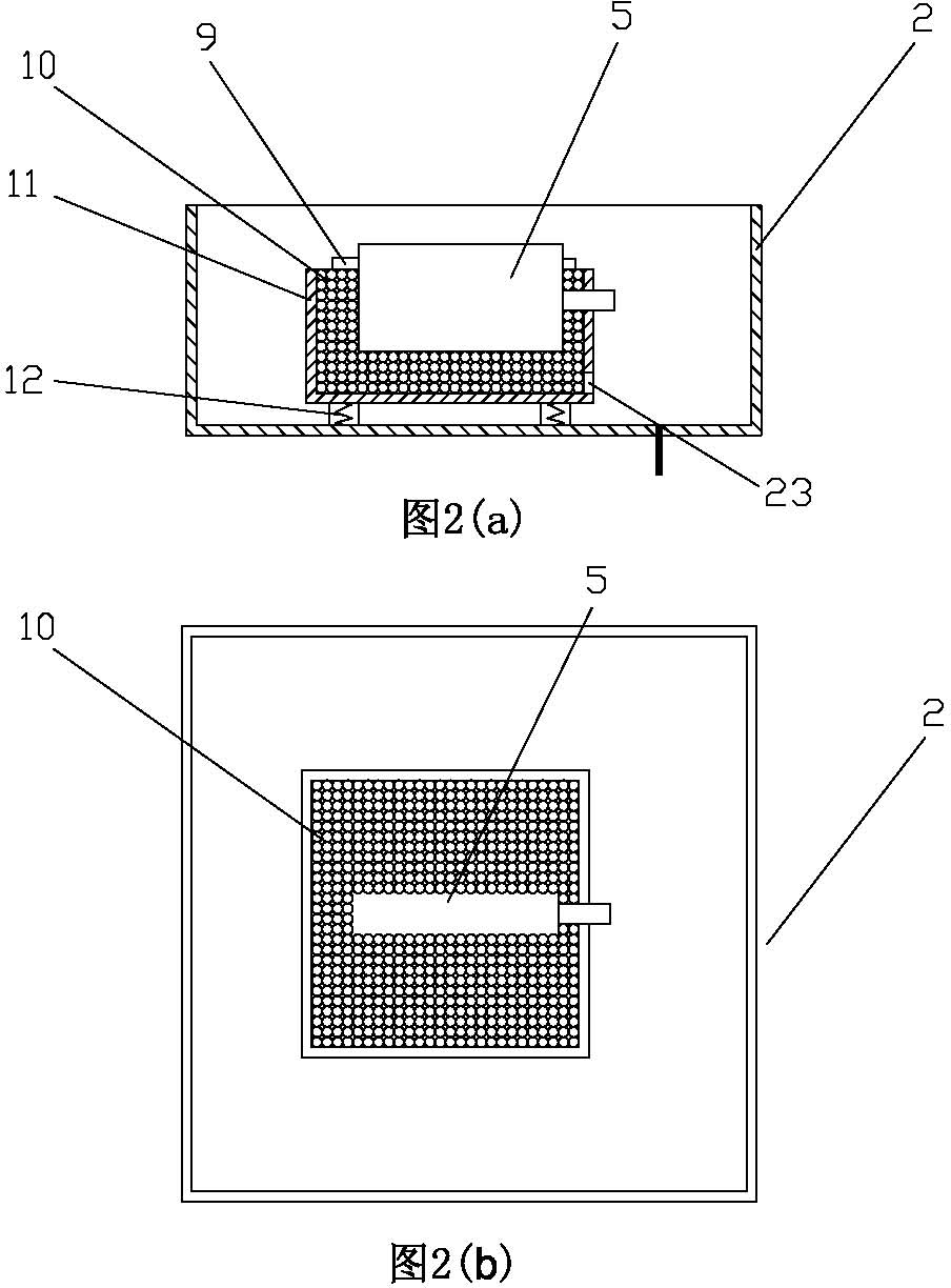
[0055] A high-speed jet jet electroforming processing device for rotating parts, which includes an electroforming power source 1, a liquid return tank 2, an electroforming core mold 5, a machine tool table movement mechanism 7, a nozzle 9 and a computer 26. The negative electrode of the power supply 1 is connected to the electroforming core mold 5 through a conductive device 4 (a brush or similar sliding conductive device can be used). The electroforming core mold 5 is installed in the electroforming tank 12 and connected to a motor that drives its rotation. 3. In order to improve the efficiency of electroforming, a vibration source 13 can be installed in the lower part of the electroforming tank 12 (which can be realized by using a vibration motor, a swing impact device, etc.). The upper surface of the electroforming tank 12 is not higher than the electroforming Friction particles 11 of core mold 5 (such as figure 2 As shown) or the friction...
PUM
 Abstract
Description
Claims
Application Information
 - R&D
- Intellectual Property
- Life Sciences
- Materials
- Tech Scout
- Unparalleled Data Quality
- Higher Quality Content
- 60% Fewer Hallucinations
Browse by: Latest US Patents, China's latest patents, Technical Efficacy Thesaurus, Application Domain, Technology Topic, Popular Technical Reports.
© 2025 PatSnap. All rights reserved.Legal|Privacy policy|Modern Slavery Act Transparency Statement|Sitemap|About US| Contact US: help@patsnap.com


