Optical sheet for controlling the direction of ray of light

An optical sheet and light technology, applied in optical elements, nonlinear optics, optics, etc., can solve the problem of ineffective viewing angle control, and achieve the effects of brightness viewing angle adjustment, brightness improvement, and uniform diffusion

Inactive Publication Date: 2011-03-30
TORAY ADVANCED MATERIALS KOREA
View PDF2 Cites 8 Cited by
  • Summary
  • Abstract
  • Description
  • Claims
  • Application Information

AI Technical Summary

Problems solved by technology

[0005] However, although the method described above is effective in controlling the viewing angle in predetermined uniform directions, it is not effective in controlling the viewing angle in irregular directions.

Method used


Image

  • Optical sheet for controlling the direction of ray of light
  • Optical sheet for controlling the direction of ray of light
  • Optical sheet for controlling the direction of ray of light

Examples


Embodiment 1

[0059] (1) Manufacture of microlens

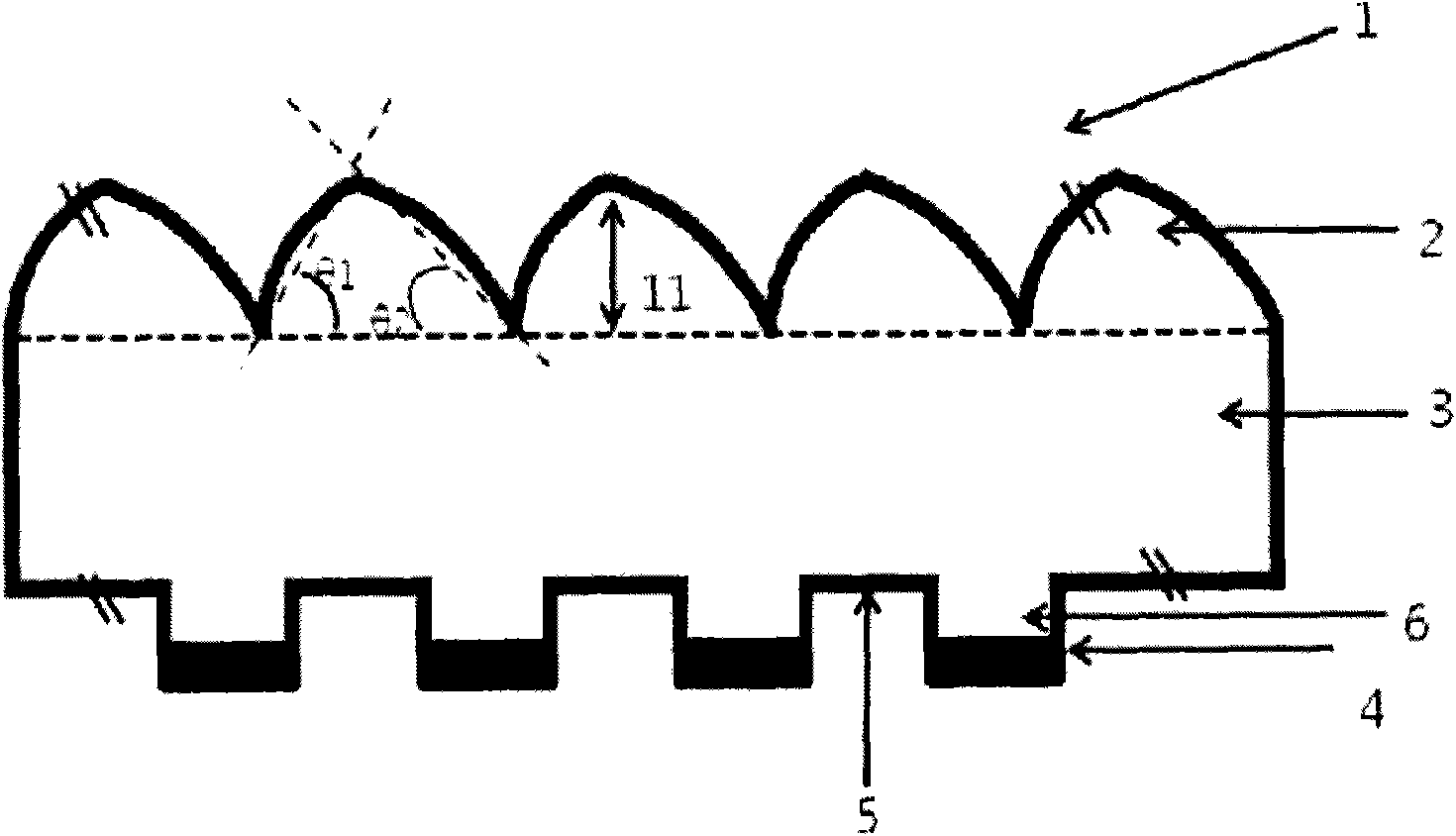
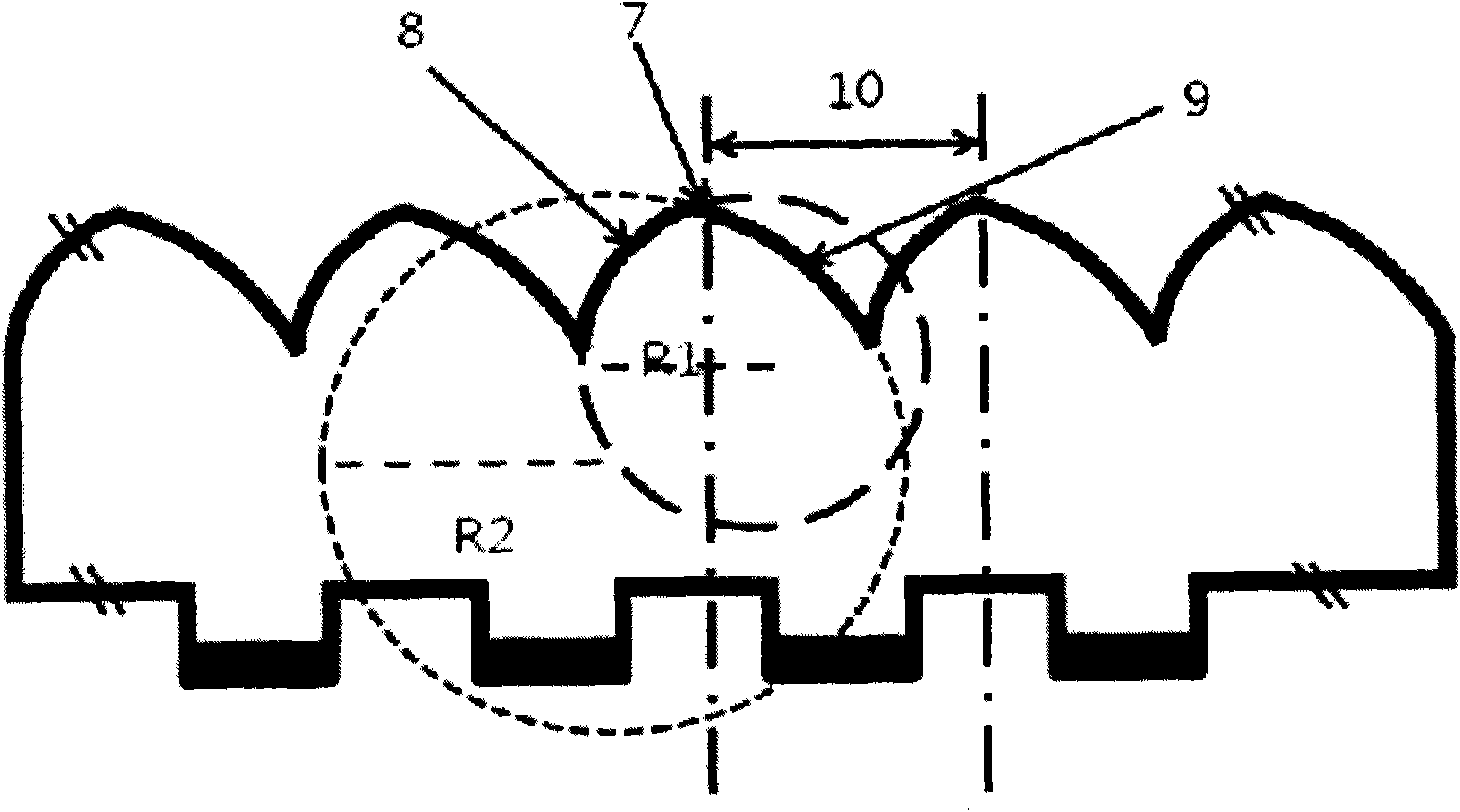
[0060] A metal mold having a pitch of 200 μm as a period was prepared using diamond bites having a curvature radius R1 of 100 μm and a curvature radius R2 of 185 μm, and the mold was filled with an ultraviolet curable resin (acrylic resin) having a refractive index of 1.54 . Next, a polyester film having a thickness of 188 μm was placed on the ultraviolet curable resin filled in the mold, and then ultraviolet rays were irradiated thereon to be cured. Afterwards, the mold is removed to obtain microlens groups.

[0061] (2) Manufacture of bumps and reflective layers

[0062] On the opposite side of the microlens group obtained in the microlens manufacturing process, a photosensitive resin was applied so that the resin thickness after drying was 40 μm. A photocuring reaction was performed using a photomask designed to form a convex pattern such that the center of each convex 6 of the reflective layer having a width of 40 μm was located at ...

Embodiment 2

[0064] (1) Manufacture of microlens

[0065] A metal mold having a pitch of 200 μm as a period was prepared using diamond teeth having a curvature radius R1 of 100 μm and a curvature radius R2 of 175 μm, and the mold was filled with an ultraviolet curable resin (acrylic resin) having a refractive index of 1.54. Next, a polyester film having a thickness of 188 μm was placed on the ultraviolet curable resin filled in the mold, and then ultraviolet rays were irradiated thereon to be cured. Afterwards, the mold is removed to obtain microlens groups.

[0066] (2) Manufacture of bumps and reflective layers

[0067] The same procedure as in Example 1 was used.

Embodiment 3

[0069] (1) Manufacture of microlens

[0070] A metal mold having a pitch of 200 μm as a period was prepared using diamond teeth having a curvature radius R1 of 100 μm and a curvature radius R2 of 165 μm, and the mold was filled with an ultraviolet curable resin (acrylic resin) having a refractive index of 1.54. Next, a polyester film having a thickness of 188 μm was placed on the ultraviolet curable resin filled in the mold, and then ultraviolet rays were irradiated thereon to be cured. Afterwards, the mold is removed to obtain microlens groups.

[0071] (2) Manufacture of bumps and reflective layers

[0072] The same procedure as in Example 1 was used.


PUM

PropertyMeasurementUnit
thicknessaaaaaaaaaa
thicknessaaaaaaaaaa
thicknessaaaaaaaaaa

Abstract

The present disclosure relates to an optical sheet for controlling the direction of light rays which is used for manufacturing backlight units of TFT-LCDs for computer monitors and televisions, and more specifically to an optical sheet which can uniformly diffuse light, improve brightness, and adjust viewing angle. There is provided an optical sheet for controlling the direction of light rays comprising a substrate film; a microlens group arranged on a first face of the substrate film; and a plurality of protuberances formed on a second face of the substrate film, wherein each protuberance comprises a reflective layer at the bottom thereof, and the plurality of protuberances comprise an aperture formed therebetween, and wherein a unit microlens of the microlens group has a first side and a second side with different radii of curvature from each other with respect to a light emission control part thereof.

Description

technical field [0001] The present invention generally relates to an optical sheet for controlling the direction of light rays, which is used to manufacture TFT-LCD (Thin Film Transistor-Liquid Crystal Display) backlight units for computer monitors, television sets, etc., and more particularly relates to an optical sheet for controlling the direction of light rays. Light source lamps positioned at the sides and back of the backlight unit provide uniform light diffusion, brightness improvement and viewing angle adjustment when light passes through it, ensuring a clearer light image and making it possible to control the direction of the light . Background technique [0002] Generally, unlike other flat panel displays, since the liquid crystal itself of the liquid crystal display is not a light-emitting element, an additional light-emitting device is required to improve the brightness of the display screen. [0003] For such a light emitting device, there are different kinds o...

Claims


Application Information

Patent Timeline
Patent Type & Authority Applications(China)
IPC IPC(8): G02B5/02G02F1/1362G02F1/1368F21V5/04
CPCG02B5/0215G02F2001/133607G02F1/133607G02B5/04G02F1/1335
Inventor 朴骏尚徐正泰李羲政李相勋柳太镛
Owner TORAY ADVANCED MATERIALS KOREA
Why Eureka
Try Eureka