
Pressing die

A compression molding and integrated technology, applied in the field of compression molding, can solve the problems of not being able to find the cutting line, affecting the appearance, and falling off, so as to avoid health threats and environmental pollution, improve enterprise production efficiency, and have neat and beautiful edges. Effect

Active Publication Date: 2011-04-06
ANHUI JINCEN COMPOSITES
View PDF3 Cites 5 Cited by
  • Summary
  • Abstract
  • Description
  • Claims
  • Application Information

AI Technical Summary

Problems solved by technology

In this process, there are the following deficiencies: First, because the upper and lower molds of the mold are generally made of epoxy resin layer, and the steel plate on the back of the mold is welded, after a long period of continuous opening and closing of the upper and lower molds, the epoxy resin layer surface It will often loosen or even fall off with the steel plate, which will affect the production efficiency of the enterprise, and even cause production accidents in serious cases; secondly, in the mold processing process, due to the epoxy resin layer used on the upper and lower surfaces of the mold, it will not last for a long time. During the processing and manufacturing, the horn-shaped protrusions on the profile surface will inevitably wear out, and the material at the tip will be worn off immediately, making it difficult or even impossible to find after pressing in the subsequent edge trimming process. The cutting line can not be better for follow-up processing; again, in the trimming process, although the trimming line is printed on the pressed formed hemp fiber board, there will be artificial errors when the staff use the jigsaw to trim the edge manually. Trimming error, resulting in uneven edges of hemp fiberboard products after trimming, which affects the appearance; finally, because the fiberboard is a wood-based panel made of interwoven cellulose fibers and using its inherent adhesive properties, it cannot be used in the subsequent polishing process. Avoid the generation of a large amount of fiber dust, which poses a threat to the health of the staff and also creates environmental pollution problems

Method used


Image

  • Pressing die
  • Pressing die
  • Pressing die

Examples


Embodiment Construction

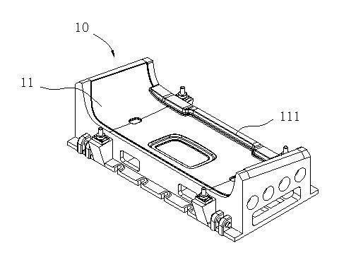
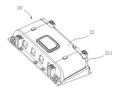
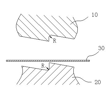
[0011] A pressing die, the pressing die includes an upper die 10 and a lower die 20, the profiles 11, 21 of the upper and lower dies 10, 20 are continuously provided with cutting edges 111, 211 that cooperate with each other along the cutting line of the product .

[0012] Further, in order to ensure that the cutting edges 111, 211 can cut edges smoothly and the edge surfaces do not interfere with each other, the mold clamping distance of the cutting edges 111, 211 is 10 to 20 wires.

[0013] Since the upper and lower molds 10, 20 are all integral cast iron structures, when processing the upper and lower molds 10, 20, you can choose to directly make the mold body by casting means, and then process its profiles 11, 21 by numerical control machining to make them The upper and lower molds 10 and 20 can be properly matched to ensure their accuracy and also solve the problem that the old-fashioned epoxy resin layer surface often loosens or even falls off between the reinforced stee...


PUM


Abstract

The invention belongs to the field of automobile interior product machining and manufacturing, in particular to a pressing die. The pressing die comprises an upper die and a lower die, and the profiles of the upper die and the lower die are provided with continuous and mutually matched cutting edges along the cutting lines of the product. When the pressing die is used, because the pressing and the edge cutting of the product are completed once, later machining is avoided and machining procedures are reduced, the production efficiency of the enterprise is increased. Meanwhile, because the continuous cutting edges directly cut off excessive materials while pressing and molding the product, the side lines of the molded product are trim and beautiful, the product does not require polishing procedure after edge cutting, and a threat to the health of workers and the pollution to the environment due to fiber dust produced by polishing are also avoided.

Description

technical field [0001] The invention belongs to the field of processing and manufacturing of automobile interior decoration products, and in particular relates to a pressing die. Background technique [0002] In the field of processing and manufacturing of automotive interior products, hemp fiberboard is widely used due to its advantages of uniform material, small vertical and horizontal strength difference, and not easy to crack. The molding surface of the existing molds for forming hemp fiber boards is generally an epoxy resin layer, and a circle of continuous angular protrusions are arranged on the molding surface of the upper mold or the lower mold along the contour line of the processed product, and the corresponding other The profile is smooth, and the back of the profile is welded and reinforced with steel plates. During production and processing, first put the hemp fiberboard into the heating room to heat. After the PP component in the hemp fiberboard is heated and ...

Claims


Application Information

Patent Timeline
IPC IPC(8): B29C43/40
Inventor 张训祥杨俊成刘超
Owner ANHUI JINCEN COMPOSITES
Learn More