Structure of direct alcohol fuel cell membrane electrode aggregate and preparation method thereof

A fuel cell membrane and aggregate technology, applied in battery electrodes, structural parts, circuits, etc., can solve problems that plague practical applications.

Inactive Publication Date: 2011-04-06
上海新微科技集团有限公司
View PDF3 Cites 34 Cited by
  • Summary
  • Abstract
  • Description
  • Claims
  • Application Information

AI Technical Summary

Problems solved by technology

However, cathode "flooding" caused by using low concentrations of methanol as fuel hampers its practical application

Method used


Image

  • Structure of direct alcohol fuel cell membrane electrode aggregate and preparation method thereof
  • Structure of direct alcohol fuel cell membrane electrode aggregate and preparation method thereof
  • Structure of direct alcohol fuel cell membrane electrode aggregate and preparation method thereof

Examples


Embodiment 1

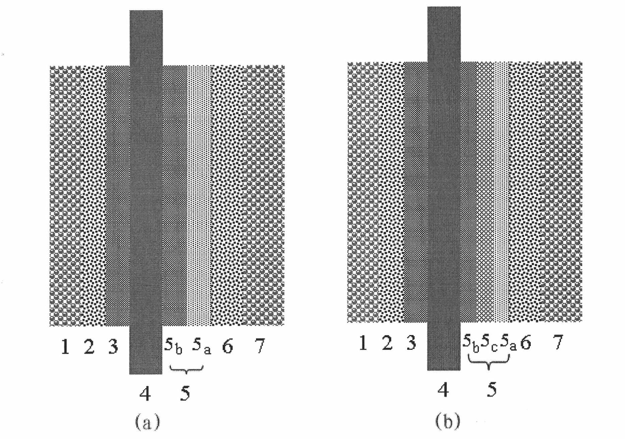
[0020] Embodiment 1 The preparation technology of the MEA of the double-layer catalytic layer cathode structure of the direct methanol fuel cell

[0021] 1. Weigh 20.0mg of Vulcan XC-72R and 36.5mg of PTFE emulsion with a mass percent concentration of 13.7% and disperse them in a mixed solution of 0.3mL of water and isopropanol (the volume ratio of isopropanol and water is 1:1), and ultrasonically Disperse for 3 hours to get a uniform carbon slurry.

[0022] 2. Take by weighing 20.0mg60wt.%Pt-Ru / C (Pt: Ru=2: 1) and 12.0mgPt-Ru black, add 50.0mg ultrapure water and all catalysts are wetted, then add 160.0mg mass percentage concentration to be 5% Nafion solution, and then add 0.4mL of water and isopropanol mixture (volume ratio of isopropanol and water is 1:1) as a dispersant, and control the temperature below 40°C for ultrasonic dispersion for 3 hours to obtain an anode catalyst ink. Weigh 20.0mg60wt.%Pt / C, add 60.0mg ultrapure water to wet the catalyst, add 50.0mg mass percen...

Embodiment 2

[0029] Example 2 Preparation Technology of MEA with Three-layer Catalytic Layer Cathode Structure of Direct Methanol Fuel Cell For the convenience of description, this embodiment takes the middle layer (C) as an example to form a three-layer catalytic layer cathode structure. If the middle layer (C) is two layers, it will constitute a four-layer catalytic layer cathode structure. Theoretically, the middle layer (C) can be multi-layered, but the components are distributed in a gradient, but considering the actual application and effect, three Layers are the most commonly used structure.

[0030] 1. Take by weighing 20.0mg Vulcan XC-72R and 36.5mg mass percent concentration and be that the PTFE emulsion of 13.7% is dispersed in the mixed solution of 0.3mL water and isopropanol (the volume ratio of isopropanol and water is 1: 1), A uniform carbon slurry can be obtained by ultrasonic dispersion for 3 hours.

[0031] 2. Weigh 20.0mg of 60wt.% Pt-Ru / C (Pt:Ru=2:1) ​​and 12.0mg of Pt...


PUM

PropertyMeasurementUnit
thicknessaaaaaaaaaa
thicknessaaaaaaaaaa

Abstract

The invention relates to a structure of a direct alcohol fuel cell membrane electrode aggregate. The membrane aggregate sequentially comprises a support layer, an anode micropore layer, an anode catalysis layer, a Nafion film, cathode catalysis layers, a cathode micropore layer and a cathode support layer. The structure is characterized in that the cathode catalysis layers are in hydrophobic and graded distribution, i.e. dual layers, three layers or multiple layers of prepared cathode catalysis layers the hydrophobicity of which is gradually changed; and a preparation method of the membrane aggregate comprises the following steps of: with carbon paper or carbon cloth as the support layer, coating a micropore dispersion layer formed by various carbon materials and a polytetrafluoroethylenebinder according to the requirements; then coating slurry formed by a precious metal-based catalyzer, Nafion resin and the like; and carrying out hot pressing on an anode and a cathode and the Nafionfilm through a proper hot treatment step and the like under certain conditions to obtain MEA (Mono Etobaccool Amine). Because the cathode catalysis layer structure in the hydrophobic and graded distribution improves the mass transfer of cathode oxygen and the catalyzer use ratio, the power density and the discharging stability are improved.

Description

technical field [0001] The invention relates to a structure and preparation method of a membrane electrode assembly capable of improving the performance and stability of a direct alcohol fuel cell. The method can effectively improve the oxygen transmission efficiency, water return ability and catalyst utilization rate of the fuel cell cathode. It belongs to the field of direct alcohol dye battery. Background technique [0002] In recent decades, as the contradiction between social and economic development, energy shortage and environmental pollution has become increasingly prominent, the development of green energy has increasingly become the focus of global attention. Fuel cells have high energy density, energy conversion efficiency, and low pollution. They are ideal power sources in the future and have attracted widespread attention from all over the world. In recent years, countries all over the world have invested a lot of manpower, material and financial resources to s...

Claims


Application Information

Patent Timeline
Patent Type & Authority Applications(China)
IPC IPC(8): H01M4/94H01M4/88
CPCY02E60/50
Inventor 杨辉陈梅黄庆红邹志青乔永进杜翀李志林
Owner 上海新微科技集团有限公司
Why Eureka
Try Eureka