Miniaturized dual-frequency antenna

A dual-frequency antenna and monopole antenna technology, applied to antennas, resonant antennas, and devices that enable antennas to work in different bands at the same time, can solve problems such as limited antenna bandwidth, inconvenient debugging, and unchanged miniaturization design, and achieve Achieve broadband impedance bandwidth, facilitate design and production, and avoid electromagnetic interference

Inactive Publication Date: 2011-04-06
HARBIN ENG UNIV
View PDF6 Cites 31 Cited by
  • Summary
  • Abstract
  • Description
  • Claims
  • Application Information

AI Technical Summary

Problems solved by technology

At the same time, solve some shortcomings of the existing dual-band antennas: (1) Most of the current dual-band antennas are in the form of monopole antennas and sleeve antennas, but the feeding methods of these antennas are relatively complicated, which is not convenient for actual debugging and production; (2) At present, most of the miniaturized dual-band antennas use the bending deformation of the monopole antenna, or use a non-planar structure, which brings certain difficulties to the design and installation of the system At the same time, it is not convenient to consider its electromagnetic compatibility characteristics, and because it adopts a non-planar structure, it is not convenient for system integration and miniaturization design; (3) Most of the current dual-band antennas have relatively narrow bandwidths, which cannot meet the current requirements. The broadband requirements of the equipment, generally each bandwidth is more than a few hundred megabytes, so it is necessary to design a dual-band antenna with a wider bandwidth; (4) In recent years, most of the antennas with dual-band Most of the antennas with special characteristics are in the form of multi-resonator elements, which generally increase the volume of the antenna and remain unchanged from the miniaturization design.
[0003] The literature "Electromagnetically coupled WLAN/WiMax antenna, M.Bashri, Ch.Ghobadi, M.Kamyab Hesari, and J.Nourinia, IEICE Electronics Express, Vol.7, No.13, 2010." proposed a dual frequency antenna, but the antenna still has a large volume and complex structure. Although the coupling method is used to generate dual-band bandwidth in this paper, the antenna adopts a double-sided coupling structure, which increases the complexity of the antenna, which is not conducive to the antenna and system integration
The document "Band-notched design of the planar monopole antenna for WLAN/WiMax applications, Kang-kang

Method used


Image

  • Miniaturized dual-frequency antenna
  • Miniaturized dual-frequency antenna
  • Miniaturized dual-frequency antenna

Examples


Example Embodiment

Specific implementation one:

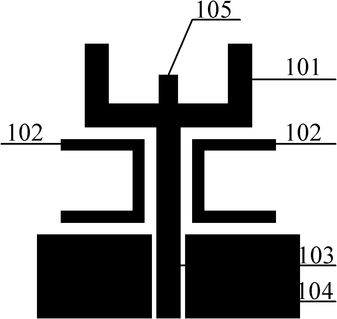
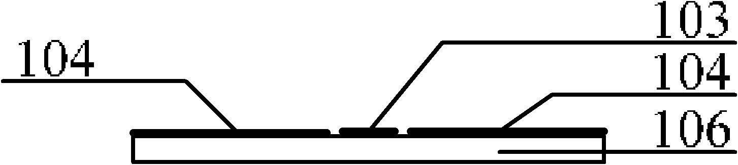
[0046] An example of the present invention is figure 1 and figure 2 shown. It consists of a dielectric substrate 106 , a U-shaped radiating element 101 , a coplanar waveguide feeding signal strip line 103 , a tuning microstrip line 105 , a U-shaped coupling radiating element 102 and a coplanar waveguide ground plane 104 . The lower end of the coplanar waveguide feeding signal stripline 103 of the antenna is connected to the SMA inner conductor. The outer conductor of the SMA is connected to the coplanar waveguide ground plane 104 . according to figure 1 and figure 2 The structure shown, as long as the appropriate size is selected, the design of the dual-frequency impedance bandwidth can be realized.

[0047] Parameter setting:

[0048] 1. Tuning the microstrip line

[0049] Tuning the microstrip line can effectively change the distributed capacitance and distributed inductance of the antenna, so that the designed antenna can meet the nee...

Example Embodiment

[0062] Implementation Example 2:

[0063] like Figure 10 As shown, another implementation example of the present invention is to use two inverted L-shaped parasitic radiating elements between the U-shaped radiating element of the antenna and the ground plane of the coplanar waveguide. By changing its size, the surface of the antenna can be effectively changed. The current distribution, thereby changing the resonant bandwidth of the antenna, enables dual-frequency operation. The antenna radiating element 201 , the coplanar waveguide feeding signal strip line 203 , the inverted L-shaped parasitic radiating element 202 , and the coplanar waveguide ground plane 204 are composed. The entire antenna is printed on a dielectric substrate with a dielectric constant of 2.65. The lower end of the coplanar waveguide feeding signal stripline 203 of the antenna is connected to the SMA inner conductor. The outer conductor of the SMA is connected to the coplanar waveguide ground plane 204...


PUM

PropertyMeasurementUnit
Thicknessaaaaaaaaaa

Abstract

The invention provides a miniaturized dual-frequency antenna. The miniaturized dual-frequency antenna comprises a medium substrate and a monopole antenna printed on the medium substrate. The monopole antenna comprises a main radiating unit, a coplanar waveguide feeding signal strip line connected with the main radiating unit, coplanar waveguide ground planes and auxiliary radiating units arrangedbetween the main radiating unit and the coplanar waveguide ground planes. The main radiating unit is a U-shaped radiating unit, the lower end of the coplanar waveguide feeding signal strip line is connected with an inner conductor of SMA (Stone Matrix Asphalt), and an outer conductor of the SMA is connected with the coplanar waveguide ground planes. The invention can be used for receiving and transmitting radio waves. The invention can be used for terminals for electronic reconnaissance and electronic countermeasure and tracking and electromagnetic protection, wireless local area network and global microwave access terminal receiving equipment. The invention has the advantages of simple structure, wide operating bandwidth and low cost, and is convenient for mass produce.

Description

technical field [0001] The present invention relates to an antenna. Specifically, it is a miniaturized dual-band antenna that can be used to receive and transmit radio waves. Background technique [0002] As radio communication equipment and electronic information equipment are developing towards multi-function, miniaturization, ultra-broadband and friendly coordination with the surrounding environment, which makes broadband, miniaturization and high gain become one of the hot topics of research at home and abroad. In recent years, coplanar waveguide structures that do not require drilling and are easy to integrate are rapidly changing, and the structures can be fabricated by photographic or lithographic techniques and have better polarization characteristics, so this technology has been applied in the design of broadband antennas and related in the design of microwave circuit components. In most cases at present, a pair of antennas is required to meet the needs of multipl...

Claims


Application Information

Patent Timeline
IPC IPC(8): H01Q1/38H01Q5/01H01Q9/30H01Q13/08H01Q5/10
Inventor 李迎松杨晓冬吴成云姜弢
Owner HARBIN ENG UNIV
Why Eureka
Try Eureka