Current limiting device with flexible switch characteristic and current limiting method

A switching characteristic and current limiting technology, applied in the field of current limiting devices, can solve the problems of poor short-circuit current effect, low utilization rate, complex mechanism, etc., and achieve the effect of improving power supply reliability and fast action speed

Inactive Publication Date: 2011-04-06
SHANDONG UNIV
View PDF4 Cites 12 Cited by
  • Summary
  • Abstract
  • Description
  • Claims
  • Application Information

AI Technical Summary

Problems solved by technology

The disadvantages of the current limiter made of superconducting materials are: complex mechanism, high price, immature technology of superconducting materials, heat dissipation when superconducting materials present large resistance
The disadvantages of the current limiter formed by the principle of series resonance are: a large capacitor bank is required, operation and maintenance are difficult, the price is expensive, and the short-circuit current cannot be limited to a small amount
The disadvantages of the existing magnetically saturated reactor current limiter are: the circuit for supplying DC current to the DC coil is complicated; the effect of limiting short-circuit current is limited; only the function of limiting short-circuit current is single;
[0007] The main purpose of the existing current limiter is simply to limit the short-circuit current. The effect of short-circuit current limitation is poor, the utilization rate is low, and the cost performance is poor, so it is difficult to popularize and apply.

Method used


Image

  • Current limiting device with flexible switch characteristic and current limiting method
  • Current limiting device with flexible switch characteristic and current limiting method
  • Current limiting device with flexible switch characteristic and current limiting method

Examples


Embodiment Construction

[0031] The present invention will be further described below in conjunction with the accompanying drawings and embodiments.

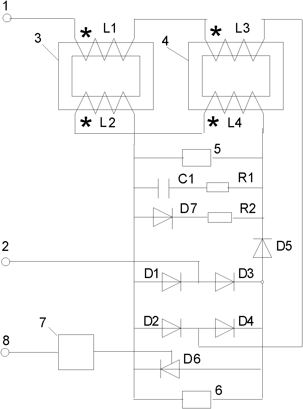
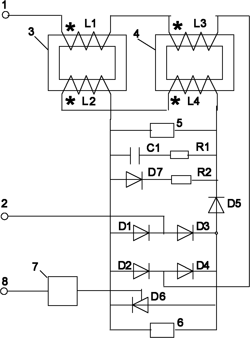
[0032] The structure and connection method of the current limiting device with flexible switching characteristics are as follows: figure 1shown. The device is connected to the transmission line in series, the input terminal 1 is connected to the power supply, and the output terminal 2 is connected to the transmission circuit. When the current limiting device with flexible switching characteristics is put into the power system in normal operation and receives a turn-on command, the control circuit 7 issues a command to turn off the thyristor D6. After the circuit breaker is closed, the current limiting device with flexible switching characteristics is connected to the transmission circuit in series, and the current passes through the coils L1 and L3 of the magnetic saturation reactor, the full bridge rectifier circuit, the diode D5, the DC coils L2 and ...


PUM


Abstract

The invention discloses a current limiting device with flexible switch characteristic and a current limiting method. The current limiting device can decrease and nearly turn off the normal load current and the short-circuit current when control equipment gives a disconnection command and can connect the normal load when the control equipment gives a connection command so that the user can use electricity normally and the performance-price ratio is relatively high. The current limiting device comprises magnetic saturable reactor iron cores I and II, a magnetic saturable reactor coil L1 and a direct-current coil L2 which are arranged on the magnetic saturable reactor iron core I, a magnetic saturable reactor coil L3 and a direct-current coil L4 which are arranged on the magnetic saturable reactor iron core II, a full bridge rectification circuit composed of diodes D1, D2, D3 and D4, two diodes D5 and D7, a thyrister D6, a control circuit, a capacitor C, and two resistors R1 and R2.

Description

technical field [0001] The invention relates to the technical field of power transmission and transformation in power systems, in particular to a current limiting device and method with flexible switch characteristics. Background technique [0002] With the continuous development of the power system and the continuous increase of power generation capacity, the short circuit current caused by the short circuit of the power system is very large. The short circuit current caused by the short circuit in the power system is very harmful to the power system. When a short circuit occurs in the power system, the relay protection device issues a trip command to trip the circuit breaker and cut off the short circuit current. The ability of the circuit breaker to cut off the short-circuit current is limited. When the short-circuit current exceeds the maximum cut-off current value of the circuit breaker, the circuit breaker cannot cut off the short-circuit current. Therefore, reducing...

Claims


Application Information

Patent Timeline
Patent Type & Authority Applications(China)
IPC IPC(8): H02H9/02
Inventor 李晓明
Owner SHANDONG UNIV
Why Eureka
Try Eureka