Eureka AIR delivers breakthrough ideas for toughest innovation challenges, trusted by R&D personnel around the world.

Vacuum/gas shield electroslag remelting continuous directional solidification device and method

A gas shielding and electroslag remelting technology, applied in the field of electroslag remelting, can solve the problems of unsuitability for ingot casting, large equipment, low efficiency, etc., and achieve the effect of improving deformation plasticity, preventing shape and distribution, and wide application fields.

Active Publication Date: 2011-04-20
BEIJING CISRI GAONA TECH
View PDF3 Cites 28 Cited by
  • Summary
  • Abstract
  • Description
  • Claims
  • Application Information

AI Technical Summary

Problems solved by technology

However, the equipment used in the traditional directional solidification process is huge, and the cost is high, the efficiency is low, and it is not suitable for the production of large-sized ingots

Method used


Image

  • Vacuum/gas shield electroslag remelting continuous directional solidification device and method
  • Vacuum/gas shield electroslag remelting continuous directional solidification device and method
  • Vacuum/gas shield electroslag remelting continuous directional solidification device and method

Examples


Embodiment 1

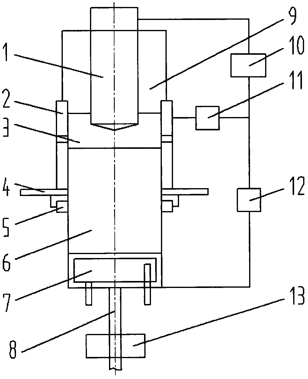
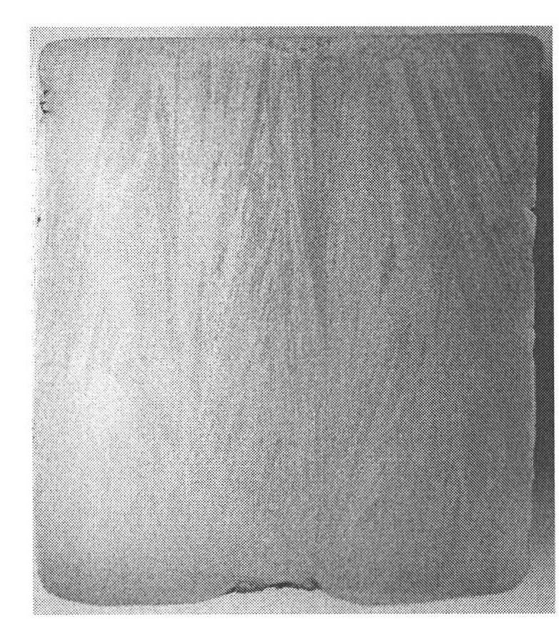
[0048] Example 1 Preparation of Φ155 FGH96 Alloy Directional Solidification Ingot .

[0049] The water-cooled crystallizer 2 has a diameter D=Φ160 mm and a height of 200 mm, and is placed on the working platform 4 .

[0050] The equipment used has a double-loop design, one loop is: transformer - self-consumed electrode - slag pool - ingot - water-cooled chassis - rectifier - transformer (called longitudinal current); the other loop is: transformer - self-consumed electrode - Slag pool—conductive module of crystallizer—rectifier—transformer (called lateral current), by controlling the distribution ratio of longitudinal current and lateral current, the slag pool can obtain a uniform temperature field, thereby further controlling the shape of the molten metal pool.

[0051]Place the water-cooled chassis 7 at the lower end of the water-cooled crystallizer 2, pour in pre-melted 100mm deep slag, insert the consumable electrode 1 with a diameter of 100mm into the slag pool 3 for ar...

Embodiment 2

[0052] Example 2 Preparation of Φ105 FGH96 Alloy Directional Solidification Ingot .

[0053] The water-cooled crystallizer 2 has a diameter D=Φ110 mm and a height of 150 mm, and is placed on the working platform 4 .

[0054] Place the water-cooled chassis 7 at the lower end of the water-cooled crystallizer 2, pour in pre-melted slag with a depth of 60 mm, insert the consumable electrode 1 with a diameter of 70 mm into the slag pool 3 for arcing, and make the consumable electrode 1 melting; when the liquid level of the slag pool 3 rises to 30mm, the ingot is drawn, and the ingot drawing speed is controlled at 2-20mm / min, which is adjusted by controlling the output voltage of the magnetic modulation transformer 10 and the insertion depth of the consumable electrode 1 into the slag pool The voltage and current of the system, in this embodiment, make the voltage 40V; then adjust the longitudinal current rectifier 12 and the lateral current rectifier 11 to control the distributio...


PUM

PropertyMeasurementUnit
diameteraaaaaaaaaa
diameteraaaaaaaaaa
diameteraaaaaaaaaa

Abstract

The invention relates to an electroslag remelting technique, in particular to a vacuum / gas shield electroslag remelting continuous directional solidification device and method. The device comprises a power supply, a consumable electrode (1), a water-cooling crystallizer (2) and a gas shield system, wherein the lower part of the water-cooling crystallizer (2) is provided with a water-cooling chassis (7) and a stripping device (13), and a two-circuit control mode is adopted by the consumable electrode (1) to make the stripping speed equivalent with the solidification speed of a cast ingot. The invention has simple operation and low cost, is convenient to control, can be used for producing large-dimension low-segregation directional solidification cast ingots and is suitable for mass production and application.

Description

technical field [0001] The invention relates to an electroslag remelting technology, in particular to a vacuum / gas protection electroslag remelting continuous directional solidification technology. Background technique [0002] Ingot billet opening is the first process of deformed alloy processing. Its purpose includes two aspects. One is to break the as-cast structure to obtain uniform and fine equiaxed grain structure and improve the plasticity of the material; the other is to change the geometry of the ingot for the next step. processing. However, for high-alloyed metal materials, such as tool and die steels, hard-to-deform superalloys, etc., due to the large amount of alloying elements, the alloy will form serious element segregation during solidification, so that coarse precipitates are formed between dendrites, and at the same time This type of alloy has a low melting point, high dynamic recrystallization temperature, poor plasticity, and a narrow optimal plastic temp...

Claims


Application Information

Patent Timeline
Patent Type & Authority Applications(China)
IPC IPC(8): C22B9/193C22B9/04B22D23/06B22D27/04
Inventor 冯涤付锐陈希春任昊
Owner BEIJING CISRI GAONA TECH
Why Eureka
Eureka Blog
Learn More