
Control method of air intake and air exhaust valves of internal combustion engine

A technology for intake, exhaust, and intake valves of internal combustion engines, applied in engine control, internal combustion piston engines, combustion engines, etc., to achieve the effects of reducing intake boost pressure, increasing overlap angle, and reducing input energy

Inactive Publication Date: 2011-04-20
DALIAN UNIV OF TECH
View PDF0 Cites 24 Cited by
  • Summary
  • Abstract
  • Description
  • Claims
  • Application Information

AI Technical Summary

Problems solved by technology

[0006] The purpose of the present invention is to solve the problem in the field of internal combustion engine research above-mentioned by selecting an appropriate variable valve system and designing a reasonable intake and exhaust valve control method to solve the problem that the internal combustion engine with a turbocharger can operate in the full range of operating conditions. well-run program

Method used


Image

  • Control method of air intake and air exhaust valves of internal combustion engine
  • Control method of air intake and air exhaust valves of internal combustion engine
  • Control method of air intake and air exhaust valves of internal combustion engine

Examples


Embodiment Construction

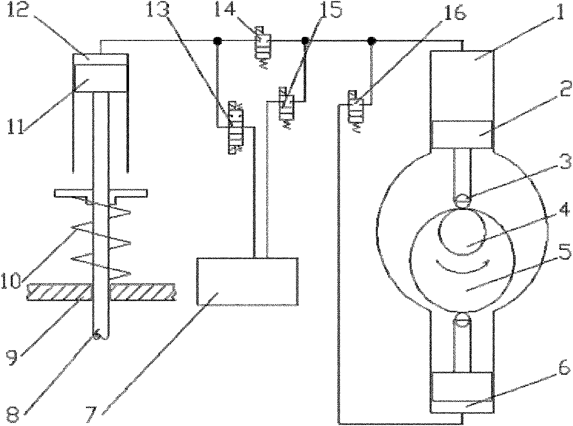
[0016] figure 1 A working principle diagram of a cam-fed electro-hydraulic intake valve drive system for a single intake valve is shown. The implementation of variable intake valve for a single intake valve is as follows:

[0017] (a) Intake valve opening: When the forward oil supply chamber 1 enters the oil supply stage, the oil supply camshaft 4 rotates, and the oil supply cam 5 pushes the oil supply plunger 2 upward, when the intake valve opening timing signal reaches , the first solenoid valve 14 is opened, the second solenoid valve 15 and the third solenoid valve 13 are closed, and the hydraulic oil pressure in the forward oil supply oil chamber 1 and the intake valve drive oil chamber 12 increases with the oil supply plunger 2 Further upward movement increases, the hydraulic pressure acting on the intake valve driving piston 11 overcomes the resistance of the intake valve spring 10, drives the intake valve 8 downward, and realizes the opening of the intake valve 8.

[...


PUM


Abstract

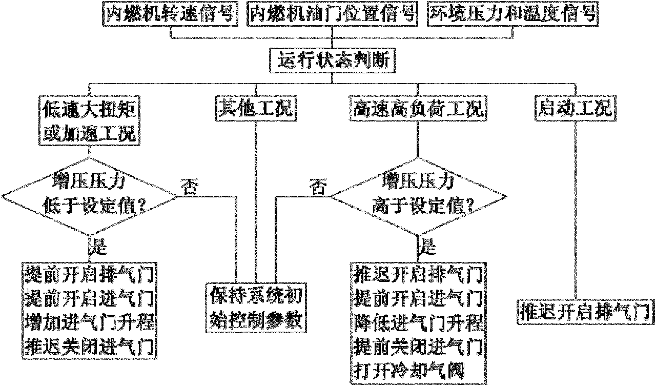
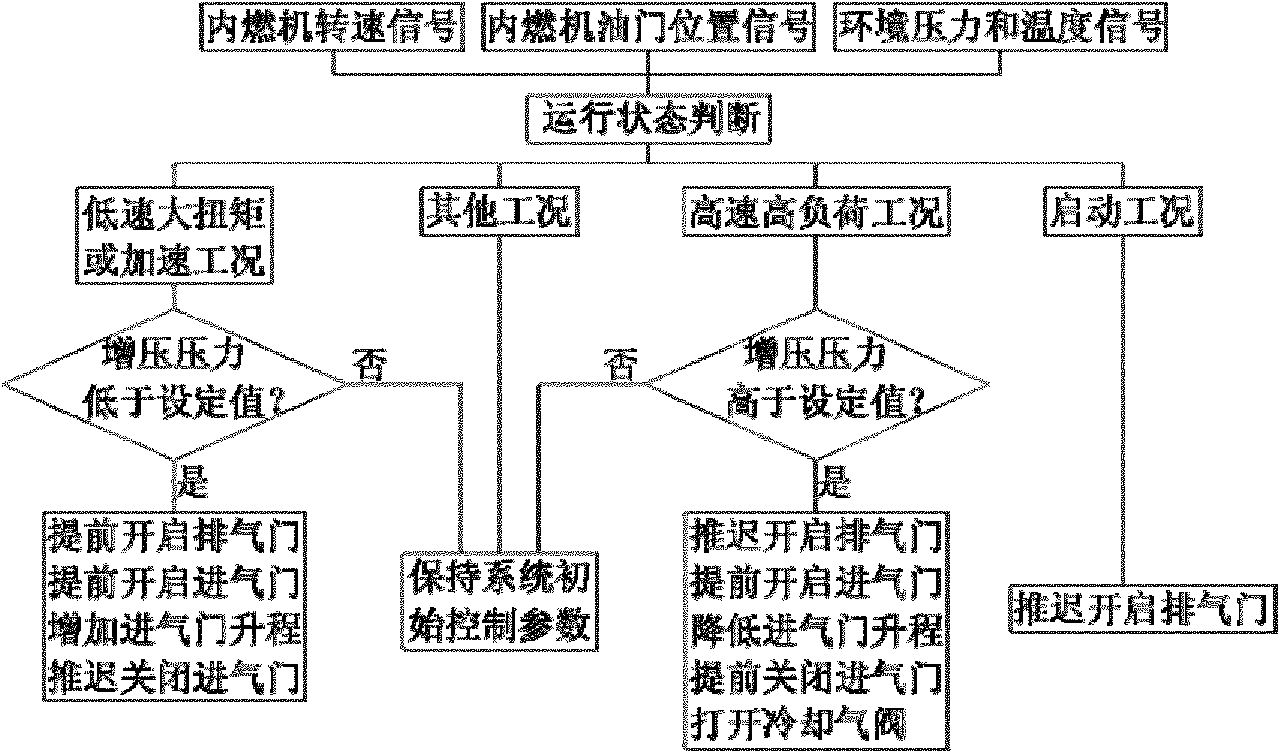
The invention provides a control method of air intake and air exhaust valves of an internal combustion engine, which belongs to the field of air intake and air exhaust systems of internal combustion engines. The control method of the air intake and air exhaust valves is based on thermodynamic cycle of high pneumatic compression ratio and low expansion ratio so as to ensure that the air exhaust valve is opened as soon as possible and the opening / closing time of the air intake valve is properly adjusted when a turbocharged internal combustion engine is under a low-speed and large-torque working condition, a highland operation working condition and an acceleration working condition, therefore, air intake flow is ensured to be increased as much as possible under the working conditions. Meanwhile, a passage is arranged between an air intake pipe behind a compressor and an air exhaust pipe before a turbocharger; air of low temperature is introduced into the air exhaust pipe to reduce exhaust temperature so as to protect the turbocharger; when cold start is carried out, the air exhaust valve is opened later to enhance compression temperature in a cylinder; and once the start is carried out, the air exhaust valve is opened early to increase the air intake quantity. The control method can largely enhance the dynamic property of the internal combustion engine under the low-speed and large-torque working condition and the highland working condition, improve the start performance and acceleration performance of the internal combustion engine and enable the internal combustion engine to obtain a better emission performance.

Description

technical field [0001] The invention relates to a method for controlling an intake and exhaust valve of an internal combustion engine, belonging to the field of intake and exhaust systems of an internal combustion engine. Background technique [0002] With the rapid increase of the number of automobiles, the continuous rise of world oil prices, and the increasingly serious air pollution, the problem of how to effectively improve the energy utilization rate of internal combustion engines and reduce emissions has become increasingly urgent. Currently there are mainly the following problems: [0003] 1) Since the new technology of turbocharging can improve the combustion rate of the internal combustion engine and reduce the emission of harmful gases, it has become a major trend in the development of internal combustion engines to equip turbochargers. However, under high speed and heavy load, the vortex The thermal and mechanical loads of the blades are too high, the torque of...

Claims


Application Information

Patent Timeline
IPC IPC(8): F01L1/34F01L9/04F01L13/00F02D13/02F01L9/10
CPCY02T10/18Y02T10/12
Inventor 隆武强崔靖晨盛凯田江平冷先银齐鲲鹏董全张强
Owner DALIAN UNIV OF TECH
Learn More