Plasma generating apparatus and plasma processing apparatus
A plasma and generating device technology, which is applied in plasma, semiconductor/solid-state device manufacturing, gaseous chemical plating, etc., to achieve the effect of simple structure, easy manufacture, and easy maintenance and inspection
- Summary
- Abstract
- Description
- Claims
- Application Information
AI Technical Summary
Problems solved by technology
Method used
Image
Examples
Embodiment 1
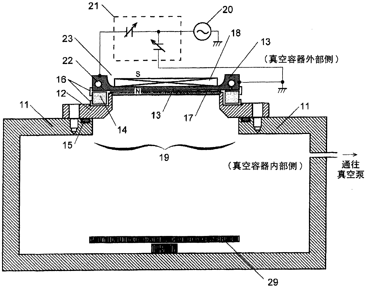
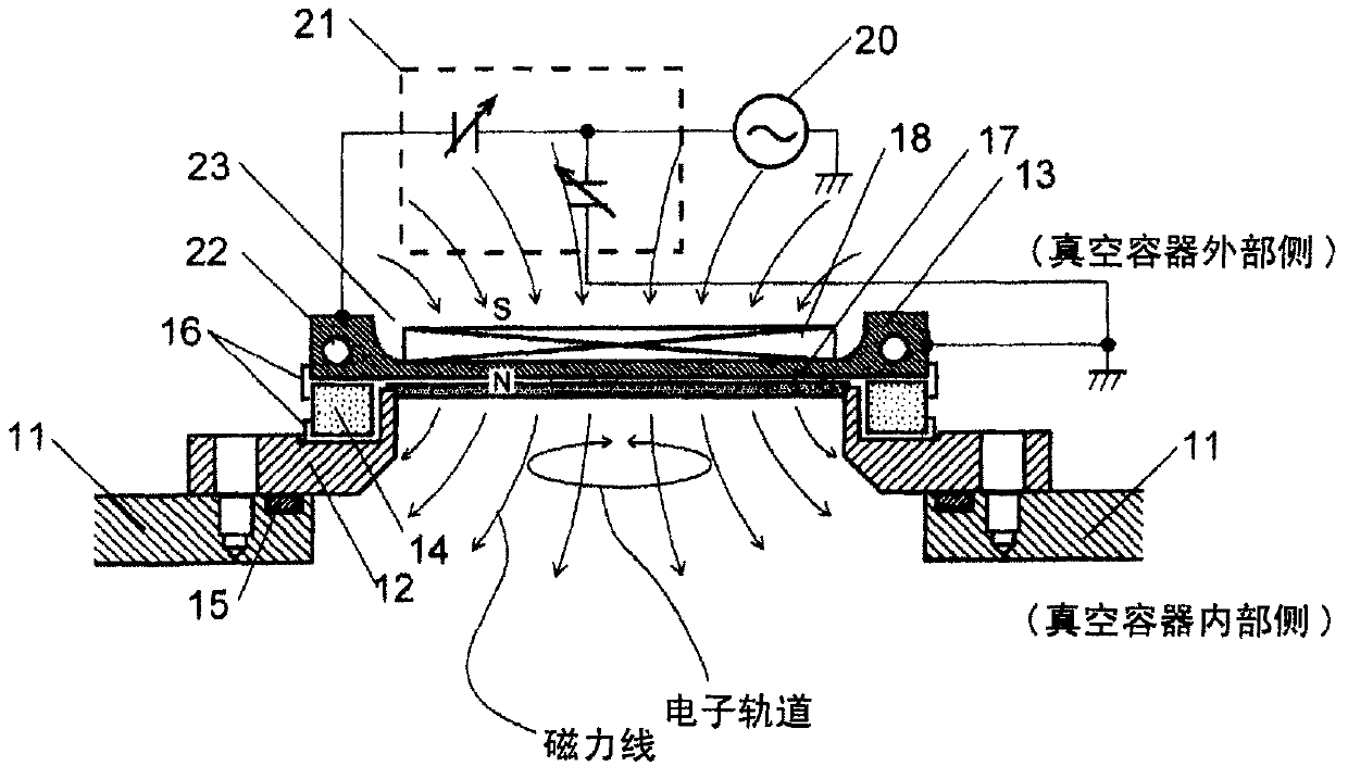
[0049] while referring to figure 1 The plasma generator of Example 1 will be described in detail. The high-frequency antenna conductor 13 is a rectangular aluminum plate with a short side of about 60 mm x a long side of about 120 mm. The surface of the high-frequency antenna conductor 13 on the vacuum side is planar, and the surface on the air side is provided with a concave notch 23 . The magnetic field generator 18 is mounted in the notch 23 . The high-frequency antenna conductor 13 is thicker around the notch 23 than the notch 23, and a water channel 22 for circulating cooling water is provided in the thicker part of the conductor. In this embodiment, the thickness of the notch 23 is set to about 3 mm so that the magnetic field enters the vacuum side through the high-frequency antenna conductor 13 and the dielectric shield plate 17 . Of course, since the required magnetic flux density will be determined by the size of the magnet, the residual magnetic flux density and th...
Embodiment 2
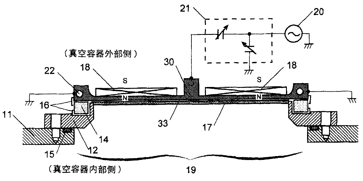
[0060] Regarding the structure near the high-frequency antenna in the plasma generating device of Embodiment 2, image 3 Shows a schematic sectional view of the main parts. The configuration of the plasma generator of this embodiment is almost the same as that of the first embodiment except for the high-frequency antenna conductor 33 and the wiring for feeding power to the high-frequency antenna conductor 33 . The length of the long side of the high-frequency antenna conductor 33 is about twice that of the high-frequency antenna conductor 13 of Embodiment 1, and a protrusion 30 for feeding high-frequency power is provided in the center, and both ends are grounded. The high-frequency power supplies power to the protrusion 30 through the matching box, and the high-frequency current flows to the grounded edges.
[0061] According to this embodiment, it is possible to roughly double the plasma generation range without increasing the impedance of the antenna.
[0062] Also, for e...
Embodiment 3
[0064] About the structure near the high-frequency antenna in the plasma generating device of embodiment 3, it is shown in Figure 4 A schematic cross-sectional view of the main parts. The present embodiment is almost the same as the first embodiment except that a high-frequency antenna conductor 43 formed of an aluminum disk having a diameter of 180 mm (among them, the diameter of the plasma generation region is 130 mm) is used. However, the magnetic field generator provided in Embodiment 1 is not used in this embodiment. In addition, according to the shape of the high-frequency antenna conductor 43, the insulating barrier frame 44 is changed into a circular ring shape, the dielectric shielding plate 47 is changed into a disc shape, and the opening 49 is changed into a circle shape, thereby respectively differing from the embodiment. 1. A point (feed point) on the disc circumference of the high-frequency antenna conductor 43 is connected to a high-frequency power supply (fr...
PUM
 Abstract
Description
Claims
Application Information
 - R&D
- Intellectual Property
- Life Sciences
- Materials
- Tech Scout
- Unparalleled Data Quality
- Higher Quality Content
- 60% Fewer Hallucinations
Browse by: Latest US Patents, China's latest patents, Technical Efficacy Thesaurus, Application Domain, Technology Topic, Popular Technical Reports.
© 2025 PatSnap. All rights reserved.Legal|Privacy policy|Modern Slavery Act Transparency Statement|Sitemap|About US| Contact US: help@patsnap.com


