Catalyst calcining box

A catalyst and calcination technology, which is applied in the direction of catalyst activation/preparation, physical/chemical process catalysts, chemical instruments and methods, etc. It can solve the problems that the box atmosphere cannot be adjusted and controlled, the equipment structure is complicated, and the temperature distribution is uneven. Uniform heating temperature distribution, slowing down exothermic reaction, slowing down and reducing the effect of thermal shock

Active Publication Date: 2011-05-04
CHENGDU DONGFANG KWH ENVIRONMENTAL PROTECTION CATALYSTS
View PDF4 Cites 3 Cited by
  • Summary
  • Abstract
  • Description
  • Claims
  • Application Information

AI Technical Summary

Problems solved by technology

The existing calcination process: the bare calcination process often faces the problems of thermal energy fluctuations and uneven temperature distribution caused by air flow; The problem that the atmosphere cannot be adjusted and controlled; some calcination processes even adopt the calcination method of inert gas protection, which increases a lot of cost and the equipment structure is complicated

Method used


Image

  • Catalyst calcining box
  • Catalyst calcining box
  • Catalyst calcining box

Examples


Embodiment 1

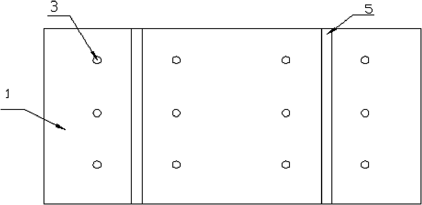
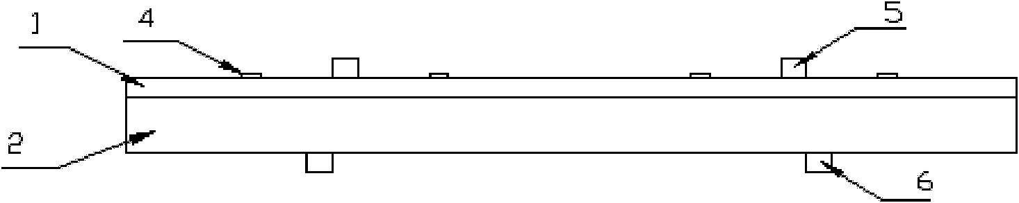
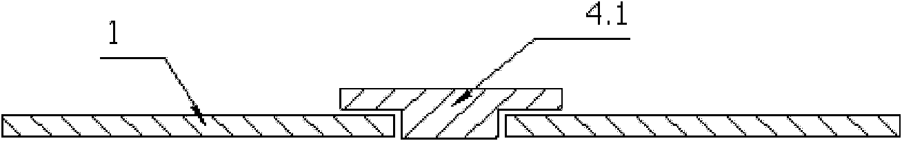
[0031] Such as figure 1 As shown, 12 vent holes are evenly arranged on the cover of the calcining box, and the diameter of the vent holes is 20mm; all 12 vent holes are covered with air hole caps, and the air hole caps are made of image 3 The shape shown in 4.1; the calcination box is evenly filled with 18×18-hole honeycomb SCR denitration catalyst dry monomer, and the calcination is carried out according to the existing calcination procedure.

Embodiment 2

[0033] On the cover of the calcining box, 4 vent holes are evenly arranged, and the vent holes are all covered with caps. Other conditions are the same as in Example 1, and calcining is carried out according to the existing calcining procedure.

Embodiment 3

[0035] The air hole cap adopts Figure 4 For the shape shown in 4.2, other conditions are the same as in Example 1, and the calcination is carried out according to the existing calcination procedure.


PUM

PropertyMeasurementUnit
diameteraaaaaaaaaa

Abstract

The invention discloses a catalyst calcining box comprising a box body and a box cover, wherein pores are evenly distributed on the box cover, each pore is provided with a pore cap, and the pore cap is matched with the pore to close the pore; under the action of airflow, the pore cap can be opened to uniaxially discharge gas in the box; the pore cap has a T-shaped cross section; and the pore cap closes the pore by self weight. The closed calcining box not only can evenly heat catalyst but also can alleviate and lower thermal shock; and the pore cap not only can prevent the undesired external gas atmosphere from entering the calcining box, but also can automatically discharge excessive gas in the box so as to control exothermal reaction. On the premise of ensuring sufficient catalyst activity, the calcination percent of pass can be greatly improved, and the calcination percent of pass is above 99% in producing honeycomb SCR (Selective Catalytic Reduction) smoke denitration catalyst.

Description

technical field [0001] The invention belongs to the design and manufacture field of catalyst production equipment, and in particular relates to the design and manufacture of a catalyst calcining box, in particular to the design and manufacture of a calcining box for producing a honeycomb SCR flue gas denitrification catalyst. Background technique [0002] The calcination process of honeycomb SCR (selective catalytic reduction) flue gas denitrification catalyst monomer is a key step in the entire catalyst production process. On the one hand, some organic additives will gradually decompose as the temperature rises during the calcination process; on the other hand, this decomposition process will undergo a strong exothermic reaction, and the exothermic reaction will increase due to the large surface area of ​​the honeycomb body. The temperature difference between the inside and outside of the honeycomb will cause irregular cracking or even breakage of the honeycomb. [0003] T...

Claims


Application Information

Patent Timeline
Patent Type & Authority Applications(China)
IPC IPC(8): B01J37/08B01J35/04
Inventor 冷洪川艾生炳梁材
Owner CHENGDU DONGFANG KWH ENVIRONMENTAL PROTECTION CATALYSTS
Why Eureka
Try Eureka