Silt solidification processor

A treatment machine and sludge technology, applied in the direction of dehydration/drying/thickened sludge treatment, etc., can solve the problems of low work production efficiency, large floor area, poor mobility, etc., achieve improved work efficiency, small floor space, prevent Effects of clogging and damaging equipment

Inactive Publication Date: 2011-05-04
无锡中科建设工程有限公司
View PDF8 Cites 21 Cited by
  • Summary
  • Abstract
  • Description
  • Claims
  • Application Information

AI Technical Summary

Problems solved by technology

[0003] In view of the shortcomings of the sludge solidification processor in the above-mentioned prior art, such as large floor space, low work production efficiency, high energy consumption, and poor mobility, the applicant provides a machine with small floor space, large processing capacity, and strong adaptability. Sludge solidification processor, thus improving work productivity and easy to move

Method used


Image

  • Silt solidification processor
  • Silt solidification processor
  • Silt solidification processor

Examples


Embodiment Construction

[0019] The specific implementation manner of the present invention will be described below in conjunction with the accompanying drawings.

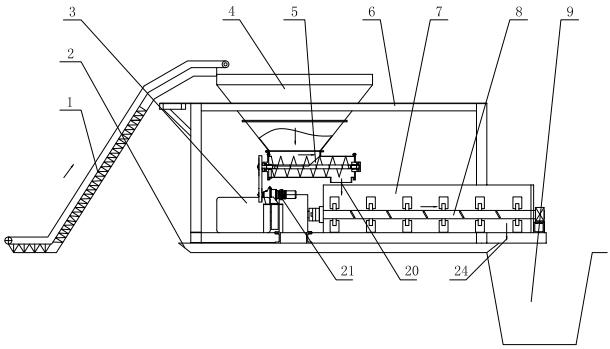
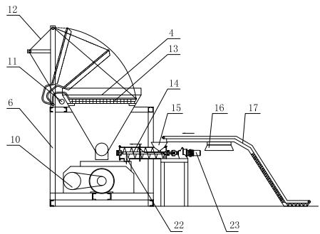
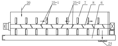
[0020] like figure 1 , figure 2 As shown, the present invention is provided with a stirring chamber 7 at the bottom of the frame 6, and the inside of the stirring chamber 7 is provided with two relatively rotating spiral stirring shafts 8 (see image 3 and Figure 4 ), the stirring shaft 8 is driven to rotate by the main motor 3 through the pulley 10, and there are two feeding ports above the initial section of the mixing chamber 7, one is the sludge feeding port 20, and the other is the curing agent feeding port 22. like figure 1 As shown, the sludge with higher water content is transported to the sludge hopper 4 on the upper part of the frame 6 through the sludge conveyor belt 1, and the bottom of the sludge hopper 4 is provided with a sludge conveying screw shaft 5, which is driven by a motor 21. The end is provided with a sludge f...


PUM


Abstract

The invention relates to a silt solidification processor which is characterized in that a stirring chamber is arranged at the lower part of a frame, two spiral stirring shafts which rotate relatively are arranged in the stirring chamber, the stirring shafts are driven by a main motor to rotate, two feed ports are arranged above the initial segment of the stirring chamber, one feed port is a silt feed port used for carrying out series connection and transportation through a silt conveyor belt, a silt hopper and a silt conveying spiral shaft, and the other feed port is a solidifying agent feed port used for carrying out the series connection and the transportation through a solidifying agent conveyor belt, a solidifying agent hopper and a solidifying agent conveying spiral shaft; and a discharge port at the tail end of the stirring chamber is arranged above a silt solidifying pond. The silt solidification processor has the advantages that the structure is compact and reasonable, the occupied area is small, and the problem that the silt solidification processor in the prior art is in a large structure requiring a lifting mechanism for conveying a solidifying agent can be improved. A flap filtering device is arranged at the inlet of the silt hopper, thereby effectively filtering and removing large solid impurities in silt in time, preventing blockage and damages to equipment and realizing low failure rate.

Description

technical field [0001] The invention relates to a sludge treatment device, in particular to a sludge solidification treatment machine. Background technique [0002] The lake and river bottom silt has a large water content, which contains not only a large amount of organic matter and rich nitrogen, phosphorus and other nutrients, but also toxic and harmful components such as heavy metals, pathogenic bacteria, and parasites (eggs); if the silt has not been treated or treated Improper treatment can easily lead to serious secondary pollution and damage to the ecological environment, polluting soil, water sources and even the food chain, so sludge disposal is particularly important. The existing mainstream sludge treatment method is to stir and mix the solidifying agent in the sludge with high water content, and after a period of flocculation and sedimentation reaction in the sludge solidification tank, it finally solidifies into a thick slurry with low water content. It can be ...

Claims


Application Information

Patent Timeline
Patent Type & Authority Applications(China)
IPC IPC(8): C02F11/14
Inventor 朱育梁
Owner 无锡中科建设工程有限公司
Why Eureka
Try Eureka