
Device and method for filling catalyst on line by pneumatic transmission

A pneumatic conveying and filling device technology, which is applied in the direction of conveying bulk materials, chemical instruments and methods, conveyors, etc., can solve the problems of large volume of flushing liquid, pipeline wear, and the inability to effectively control the solid content of conveying slurry, etc. , to achieve the effect of stable conveying and simple structure

Active Publication Date: 2011-05-11
CHINA PETROLEUM & CHEM CORP +1
View PDF3 Cites 12 Cited by
  • Summary
  • Abstract
  • Description
  • Claims
  • Application Information

AI Technical Summary

Problems solved by technology

Its advantages are short process flow, simple structure, flexible layout, and easy automation; its disadvantages are pipeline wear, material crushing, and the system needs to be explosion-proof
[0004] Chinese patent ZL200420086396.8 (CN2764742Y) discloses a surge type pneumatic conveying device, which is composed of a storage bin, a sending tank, a gasification nozzle and multiple sets of valves, with a complex structure and poor reliability
Chinese patents 200510059627.5 (CN1686603A), 99104300.6 (CN1259478A) disclose a catalyst particle counter pressure conveying method and its device, including an upper container, an intermediate container and a lower container, which are composed of decompression, charging, pressurizing and unloading Four processes, the process is more complicated
This process requires online injection of the catalyst. If only hydraulic flushing is implemented, a high-temperature, high-pressure pump needs to be installed, and the solid content of the transported slurry cannot be effectively controlled: when the solid content is high during the flushing process, it is easy to block the pipeline and cause wear and tear. For valves and equipment, when the solid content rate in the flushing process is too low, the required flushing liquid volume is large, which has a great influence on the boiling state and temperature field of the reactor

Method used


Image

  • Device and method for filling catalyst on line by pneumatic transmission
  • Device and method for filling catalyst on line by pneumatic transmission
  • Device and method for filling catalyst on line by pneumatic transmission

Examples


Embodiment Construction

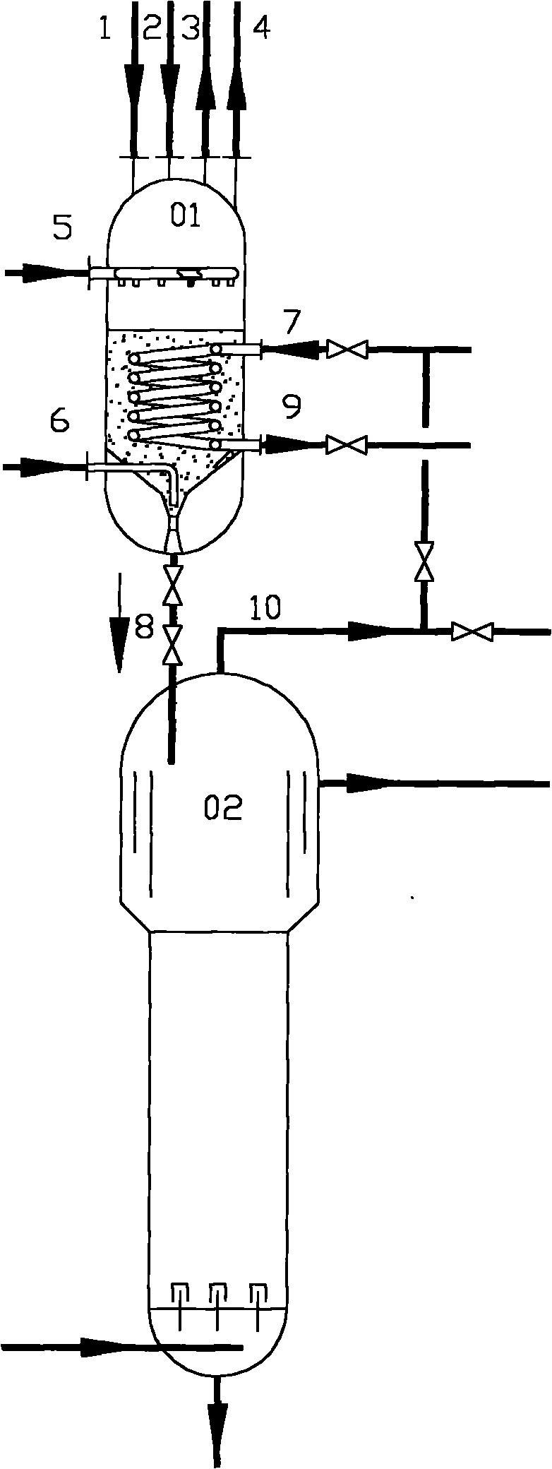
[0017] The online catalyst filling device of the present invention can use high-pressure hydrogen as the transmission power source to realize online filling of the catalyst. According to the catalyst online filling process provided by the present invention, it consists of four steps: catalyst dosing, gas replacement, catalyst preheating and catalyst filling; at the same time as catalyst dosing, nitrogen is injected to separate catalyst dust; Reactor gas phase product.

[0018] The present invention will be described in further detail below in conjunction with the accompanying drawings.

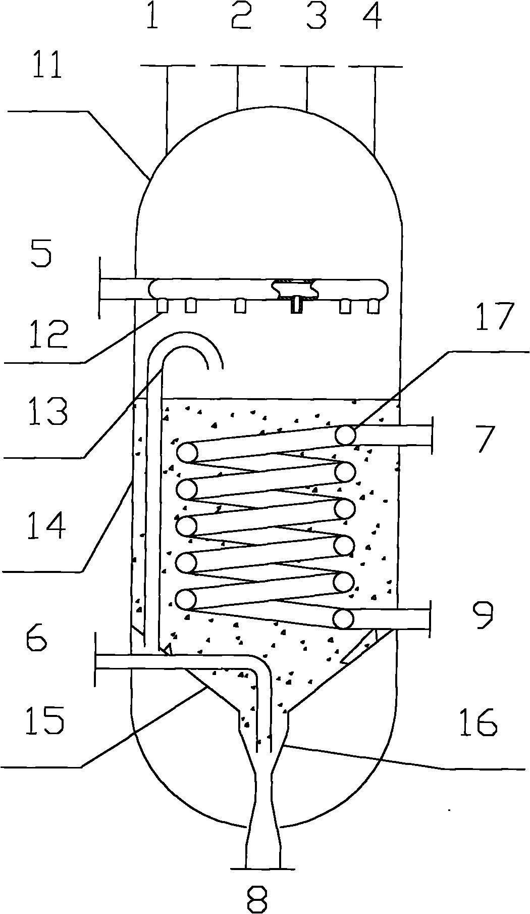
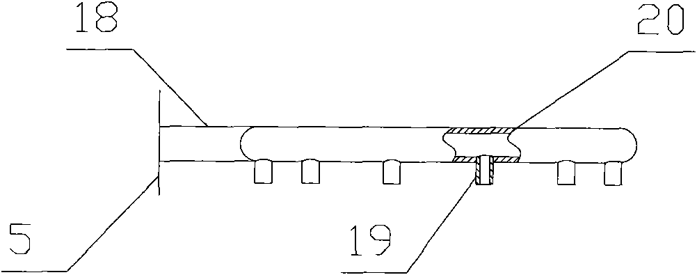
[0019] Such as figure 1 As shown, the online catalyst filling device of the present invention includes a catalyst filling tank 01, and the catalyst filling tank 01 and the ebullated bed reactor 02 are arranged up and down. The catalyst outlet 8 of the catalyst filling tank is connected to the top nozzle of the ebullated bed reactor through the process pipeline; the heat medium inlet 7 of the...


PUM


Abstract

The invention relates to a device and a method for filling a catalyst on line by pneumatic transmission. The filling device comprises a catalyst filling tank. The filling tank comprises a cone flow guide body, a nitrogen distributor, an ejector and a heating coil. The cone flow guide body is positioned in a lower sealing end of an equipment cylinder. The heating coil is positioned on the middle lower part of the equipment cylinder. The ejector is positioned at the bottom of the cone flow guide body and comprises a gas transmission pipe, an ash bin, a contraction segment, a choke tube, an expansion segment and a joint pipe sequentially from top to bottom. The on-line filling of the catalyst can be realized by filling high pressure hydrogen into the ejector, pumping catalyst particles into the ejector and making the catalyst particles enter a reactor under the drive of hydrogen flow. The device has a simple structure and does not need transferring oil. The transferring process is stable. A pipeline cannot be blocked. The device is suitable for continuously or discontinuously filling the fresh catalyst into the fluidized bed reactor on line.

Description

technical field [0001] The invention relates to an online filling device and method for pneumatic conveying catalyst, which belongs to the field of petrochemical industry and is suitable for adding catalyst into a reactor, especially for adding catalyst online into an ebullated bed reactor. Background technique [0002] Solid particle transportation problems exist in petrochemical, environmental protection, mining metallurgy, electric power and other fields. Generally, solid particle conveying methods include mechanical conveying, air conveying and hydraulic conveying. [0003] The use of hydraulic transportation to transport solid particles to the closed system usually requires a pulping process, and a slurry pump is used to inject it into the equipment. There are complicated procedures, a large number of equipment, large power consumption, serious wear of the pump, short operating cycle, and a large amount of maintenance. , high operating costs and other shortcomings. At...

Claims


Application Information

Patent Timeline
Patent Type & Authority Applications(China)
IPC IPC(8): B01J8/24B65G53/04
Inventor 方向晨齐慧敏彭德强李欣
Owner CHINA PETROLEUM & CHEM CORP
Learn More