
Oil-water interface measuring device of crude oil storage tank and measuring method thereof

A crude oil storage tank, oil-water interface technology, used in measuring devices, lubrication indicating devices, liquid/fluid solids measurement, etc., to achieve the effect of improving the level of modernization and informatization, improving measurement accuracy, and realizing comprehensive automation

Inactive Publication Date: 2011-05-11
SHAANXI UNIV OF SCI & TECH
View PDF3 Cites 21 Cited by
  • Summary
  • Abstract
  • Description
  • Claims
  • Application Information

AI Technical Summary

Problems solved by technology

[0005] In view of the characteristics of the "three highs" of high wax, high viscosity and high coagulation in most oilfields in my country, there is currently no practical solution to the device and system for high-precision oil-water interface measurement and control under long-term use. A method must be found to solve the problem. For the above problems, the measurement of each interface of the oil layer is completed, and the real-time monitoring of parameters such as the oil-water interface in the crude oil storage tank, the thickness of the oil-water transition zone, the distribution of water content at each medium layer, the height of the liquid level, and the height of the water level is realized. and linked with the production system to realize the functions of automatic oil discharge and automatic drainage; stable, reliable, long-life and maintenance-free operation in the environment of viscous, hanging material, wax deposition, etc.

Method used


Image

  • Oil-water interface measuring device of crude oil storage tank and measuring method thereof
  • Oil-water interface measuring device of crude oil storage tank and measuring method thereof
  • Oil-water interface measuring device of crude oil storage tank and measuring method thereof

Examples


Embodiment Construction

[0026] The present invention is described in further detail below in conjunction with accompanying drawing:

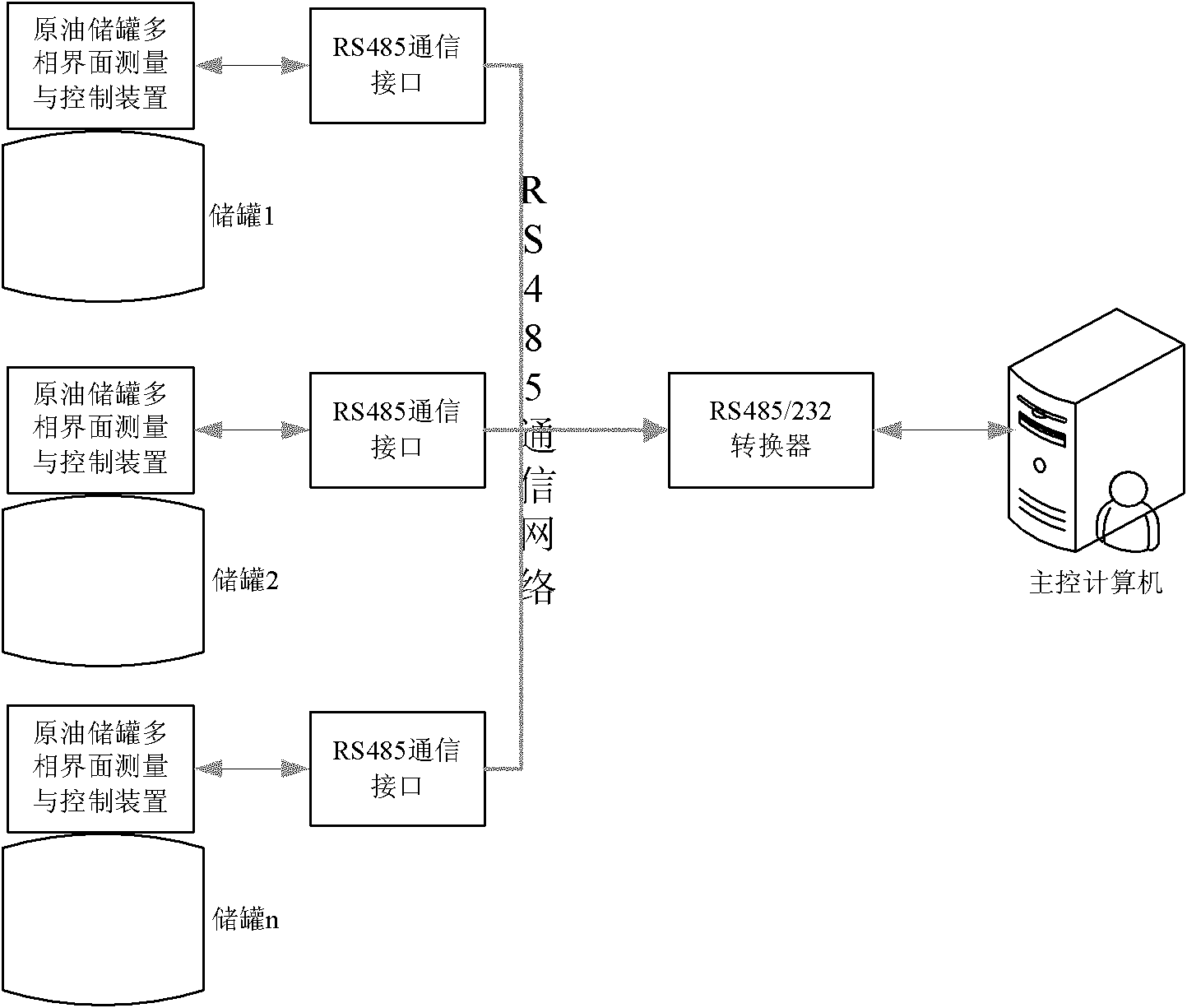
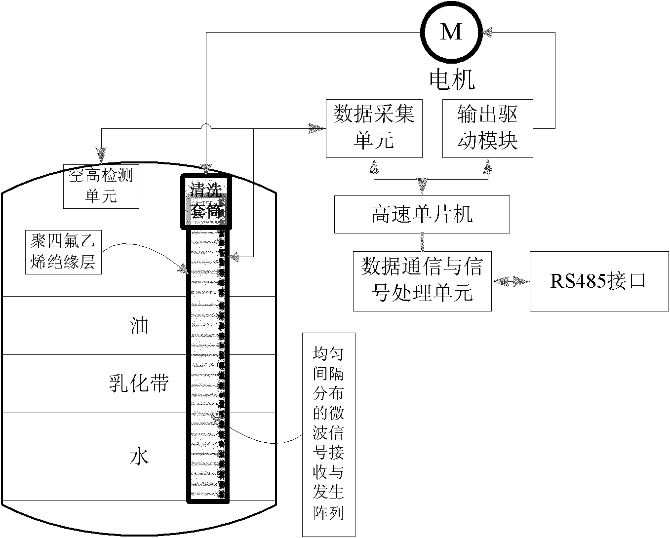
[0027] see figure 1 The oil-water interface measurement system of the crude oil storage tank includes a main control computer, an RS485 communication network and an on-site measurement and control device. The main control computer is an industrial PC and the corresponding software system. The main control computer is connected to the RS485 communication network through the RS485 / 232 converter, and the RS485 communication network is connected to multiple on-site measurement and control devices through the RS485 communication interface. The on-site measurement and control device includes a data communication and signal processing unit, a single-chip microcomputer, a data acquisition unit, a single-chip microcomputer output drive module, a measurement array probe jacket cleaning unit, an empty height detection unit and a multi-phase interface tomography unit. The data ac...


PUM


Abstract

The invention discloses an oil-water interface measuring device of a crude oil storage tank and a measuring method thereof. The oil-water interface measuring device comprises a main control computer, an RS485 (Recommended Standard 485) communication network and field measurement and control devices, wherein the main control computer is connected onto the RS485 communication network which is connected with the plurality of field measurement and control devices by RS485 communication interfaces; and each field measurement and control device comprises a data communication and signal processing unit, a single chip microcomputer, a data acquisition unit, an output driving module of the single chip microcomputer, a measuring array probe sheathed cleaning unit, a space height detection unit and a matrix type multi-phase interface tomoscan unit. The invention integrates the advanced sensor technology, data acquisition, modern communication and the computer control technology so as to realize comprehensive automation of measurement of the storage tank, greatly improves the accuracy of measurement, liberates workers from heavy work, leads workers to be capable of browsing and inquiring measured data and curves on the internet, and can improve modernization and informationization level of control and management of the production process of oil production plants in an oil field.

Description

technical field [0001] The invention belongs to the technical field of petroleum equipment, and relates to an oil-water interface measuring device, in particular to a crude oil storage tank oil-water interface measuring device and method. Background technique [0002] Most of the newly mined crude oil contains a large amount of water, sediment, and natural gas. In order to separate water, gas, and sediment, the crude oil should be transported to an oil storage tank at a high temperature of 80°C for more than 48 hours for separation. This work is done in the oil field The most important part is the oilfield dehydration station, through heating, cement sand, water oil, oil gas and other interfaces will be formed in the oil storage tank. In order to improve the efficiency of the oil storage tank and understand the height of the oil layer in the oil storage tank, it is necessary to accurately measure the oil-gas interface of the upper interface of the crude oil, so as to safely ...

Claims


Application Information

Patent Timeline
Patent Type & Authority Applications(China)
IPC IPC(8): G01F23/284
Inventor 杨帆张彩丽任喜伟
Owner SHAANXI UNIV OF SCI & TECH
Learn More