
Laser ultrasonic detection system and detection method thereof

A detection system, ultrasonic technology, applied in the direction of measuring devices, geophysical measurement, instruments, etc., can solve the problems of low measurement efficiency, poor coupling effect between probe and model surface, easily damaged probe, etc., and achieve realistic simulation effect

Active Publication Date: 2011-05-11
CHINA PETROLEUM & CHEM CORP +1
View PDF2 Cites 26 Cited by
  • Summary
  • Abstract
  • Description
  • Claims
  • Application Information

AI Technical Summary

Problems solved by technology

[0007] However, piezoelectric ultrasonic probes are far from meeting the above requirements when testing solid geological models, especially complex surface models.
Due to the large contact surface of the device detection part due to the process, when the curved surface model is tested, the coupling effect between the probe and the model surface is poor; because the existing ultrasonic probe can only transmit and receive narrowband, the measurement cannot reflect the wideband construction in the field. The actual situation received
In addition, because it is a contact measurement, the measurement efficiency is low and the accuracy is poor if the manual method is used; when moving by mechanical means, the process of pulling up and placing must be repeated every time, and the contact pressure between the probe and the model at each placement point is very high. Difficult to achieve consistency, so the repeatability of the measurement is poor, and the probe is easy to damage
At present, a complete test of a set of solid geological models often takes several months, which is far from meeting the needs of scientific research and production
In addition, general probes can only emit or detect vibration in one direction, and cannot simulate the situation where three component signals are simultaneously transmitted and received in field three-component exploration

Method used


Image

  • Laser ultrasonic detection system and detection method thereof
  • Laser ultrasonic detection system and detection method thereof
  • Laser ultrasonic detection system and detection method thereof

Examples


Embodiment Construction

[0049]The laser ultrasonic seismic model detection system consists of a laser detection part, an ultrasonic emission part, a three-dimensional coordinate instrument platform and a high-speed analog-to-digital converter, which can perform non-contact high-speed ultrasonic detection of solid geological models. Its implementation is as follows:

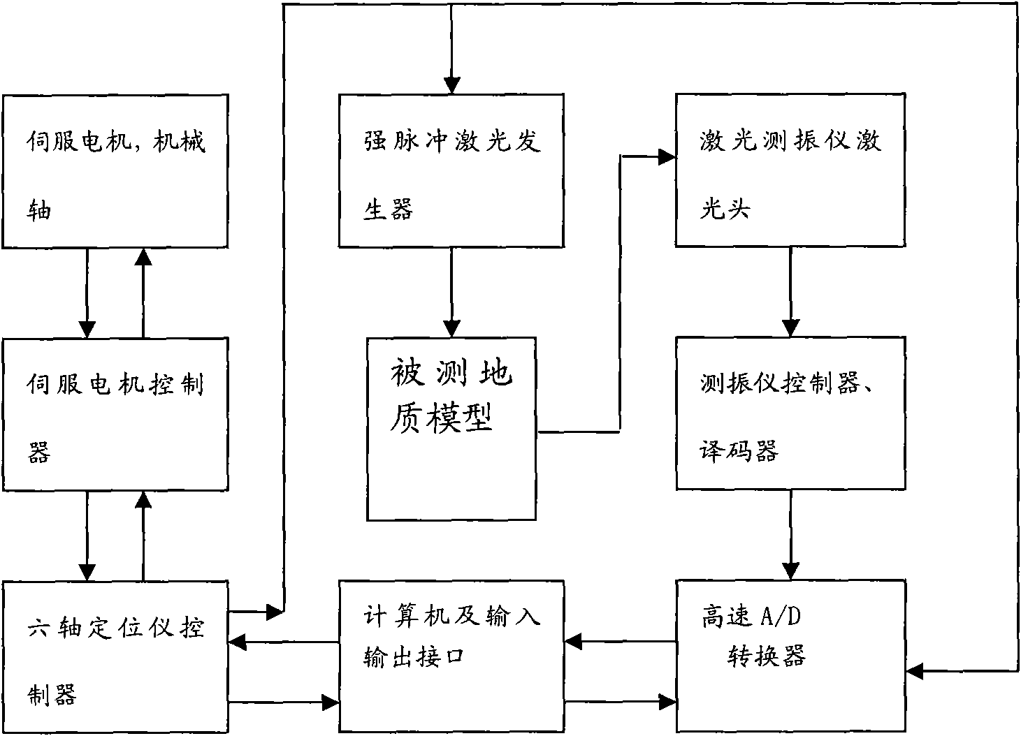
[0050] The system includes the hardware architecture of the laser ultrasonic seismic model detection system composed of an intense pulsed laser source, a laser Doppler vibrometer, a high-speed analog-to-digital converter, a computer and a three-dimensional coordinate instrument;

[0051] The launch part of the system uses an intense pulsed laser source. When testing the model, the intense pulsed laser source emits laser pulses to a certain point of the model (also known as the shot point), and the point will expand or melt when heated, thereby generating ultrasonic waves and transmitting them to the inside of the model. In this way, mul...


PUM


Abstract

The invention relates to a laser ultrasonic detection system and a detection method thereof. The system is used for generating and receiving field seismic exploration seismic waves simulated by an ultrasonic method under the indoor condition. A complete set of laser ultrasonic automatic acquisition system comprises a set of intense pulse laser source, a single-point laser Doppler seismograph, a three-dimensional laser Doppler seismograph, a 24-bit analog-to-digital converter, a three-dimensional coordinatograph and the like. The system solves the problems of a large number of conventional geologic model simulation methods, can perform single-point and three-component non-contact ultrasonic detection, and meets the requirement of modern geophysical exploration on fine and multi-component simulation.

Description

technical field [0001] The invention belongs to the field of seismic physics research, and relates to a laser ultrasonic detection device, in particular to a system for simulating the generation and reception of seismic waves in field seismic exploration under indoor conditions by using an ultrasonic method, and belongs to the field of laser vibration detection. Background technique [0002] Earthquake physical simulation research refers to the use of physical models to study earthquakes and related phenomena, especially fluctuation phenomena. It is an important part of experimental geology, also known as model geology. The most commonly used method in model geology studies is the ultrasonic method, and is therefore often referred to as ultrasonic seismic modeling. Ultrasonic seismic physical model experiments conduct indoor simulation observations of the propagation of seismic waves in various complex geological bodies through the observation of ultrasonic propagation in ge...

Claims


Application Information

Patent Timeline
IPC IPC(8): G01V1/00G01V1/02G01V1/18
Inventor 宗遐龄赵群李守才马国庆王辉明张国保黄德娟邵志东傅星菊薛诗桂
Owner CHINA PETROLEUM & CHEM CORP
Learn More