Supercharge Your Innovation With Domain-Expert AI Agents!

Optical fiber sensing head with nano grid structure

An optical fiber sensing head and nanogrid technology, applied in the field of optical fiber sensing heads, can solve the problems of affecting resonance peaks, low excitation efficiency, bulky sensing device, etc., and achieve increased scattering cross-section, high sensitivity, localization Field enhancement effect

Active Publication Date: 2011-05-18
HUAZHONG UNIV OF SCI & TECH
View PDF3 Cites 4 Cited by
  • Summary
  • Abstract
  • Description
  • Claims
  • Application Information

AI Technical Summary

Problems solved by technology

However, there are various problems: 1. The sensing device is bulky; 2. The resonance wavelength is inconsistent with the excitation wavelength, and the excitation efficiency is low; 3. The polarization of the light source affects the resonance peak, thereby affecting the instability of the enhancement factor.

Method used


Image

  • Optical fiber sensing head with nano grid structure
  • Optical fiber sensing head with nano grid structure
  • Optical fiber sensing head with nano grid structure

Examples


Embodiment 1

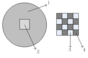
[0016] Such as figure 1 As shown, the optical fiber sensing head of the present embodiment comprises cladding (1) and fiber core (2), and described cladding (1) is the cylinder that diameter is 126 μ m, and refractive index is 1.65, and described fiber core (2) The cross-section is rectangular, with a size of 6 μm×6 μm. It is formed by a plurality of two glass materials (3, 4) with refractive indices of 1.5 and 1.7 arranged alternately on the xy plane. The cross-sections of the glass materials (3, 4) are 200nm×200nm rectangle, so that the rectangular fiber core section is divided into a grid of 30×30 arrays. On one end section of the fiber core (2), all low-refractive index glass material (3) end faces are etched to a depth of 10 nm along the axial direction z, while the unetched high-refractive index material (4) is etched away along the axial direction z Z is plated with a rectangular Au film with a size of 200nm and a thickness of 60nm. The length of the entire sensor hea...

Embodiment 2

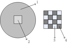
[0018] The optical fiber sensing head of this embodiment comprises a cladding (1) and a fiber core (2), the cladding (1) is a cylinder with a diameter of 126 μm and a refractive index of 1.67, and the cross section of the fiber core (2) is rectangular , with a size of 6 μm × 6 μm, formed by alternate arrangement of two glass materials (3, 4) with refractive indices of 1.51 and 1.74 respectively on the xy plane, and the cross-sections of the glass materials (3, 4) are all 200 nm × 200 nm , so that the rectangular core section is divided into a grid of 30×30 arrays. On one end section of the fiber core (2), all low-refractive index glass material (3) end faces are etched to a depth of 20 nm along the axial direction z, while the unetched high-refractive index material (4) is etched away along the axial direction z Z is coated with a rectangular Au film with a size of 200nm and a thickness of 50nm. The length of the entire sensor head in the axial z direction is 70 μm.

[0019]...


PUM

PropertyMeasurementUnit
Thicknessaaaaaaaaaa
Thicknessaaaaaaaaaa
Lengthaaaaaaaaaa

Abstract

The invention discloses an optical fiber sensing head with a nano grid structure, comprising a covering layer (1) and a fire core (2), wherein the fire core (2) is formed by alternative arrangement and combination of two glass materials with different refractive indexes and same length; the sections of two glass materials are all rectangular; and the section of the formed fire core (2) is shaped like a grid-shaped rectangle. The optical fiber sensing head is characterized in that the surface of the section of one end of the fire core (2) is level to form a smooth surface and is used for being fused with common optical fiber; and the end parts of all the glass materials with low refractive index on the section of the other end of the fire core (2) are etched by certain depth, and the end parts of all the glass materials with high refractive index are plated with a layer of metal film, so that the section of the fire core (2) forms rough surfaces with different heights. The optical fiber sensing head has the advantages of stable working and high sensitivity, and effective research means in the fields such as mine safety, air pollution and biomolecule detection and the like are provided.

Description

technical field [0001] The invention relates to the field of optical fiber sensors, in particular to an optical fiber sensor head with a nano grid structure. Background technique [0002] Optical fiber sensor is to use optical fiber technology and optical principle to convert the sensed measurement into usable output signal. Optical fiber sensors can be used to measure a variety of physical quantities, such as sound field, electric field, pressure, temperature, angular velocity, acceleration, etc., and can also complete measurement tasks that are difficult to complete with existing measurement technologies. In a narrow space, in the environment of strong electromagnetic interference and high voltage, fiber optic sensors have shown unique capabilities. At present, the optical fiber sensing head includes: contact type optical fiber liquid level sensor sensing head, optical fiber current sensor sensing head, metal material corrosion fiber grating sensing head, optical fiber te...

Claims


Application Information

Patent Timeline
IPC IPC(8): G02B6/255G02B6/25G01N21/65
Inventor 鲁平田铭刘德明
Owner HUAZHONG UNIV OF SCI & TECH
Features
  • R&D
  • Intellectual Property
  • Life Sciences
  • Materials
  • Tech Scout
  • Unparalleled Data Quality
  • Higher Quality Content
  • 60% Fewer Hallucinations
Learn More