
Horizontal convection integral grain drying machine

A drying machine and grain technology, applied in the direction of drying and preserving seeds, etc., can solve the problems of low temperature, large energy consumption, high cost, etc.

Inactive Publication Date: 2011-05-25
HARBIN ZHONGSHENGLONG HEATING EQUIP TECH DEV
View PDF4 Cites 19 Cited by
  • Summary
  • Abstract
  • Description
  • Claims
  • Application Information

AI Technical Summary

Problems solved by technology

[0003] The present invention aims to solve the problem of backward technology of existing tower dryers, high cost, low efficiency, low temperature and slow heating speed, large energy consumption, polluting emissions, easy to cause burnt grains and string of smoke, resulting in dryness after drying. For the problem of reduced grain quality, a horizontal convection integrated grain dryer is now provided. The specific technical solution to solve the above problems is as follows:

Method used


Image

  • Horizontal convection integral grain drying machine
  • Horizontal convection integral grain drying machine
  • Horizontal convection integral grain drying machine

Examples


specific Embodiment approach 1

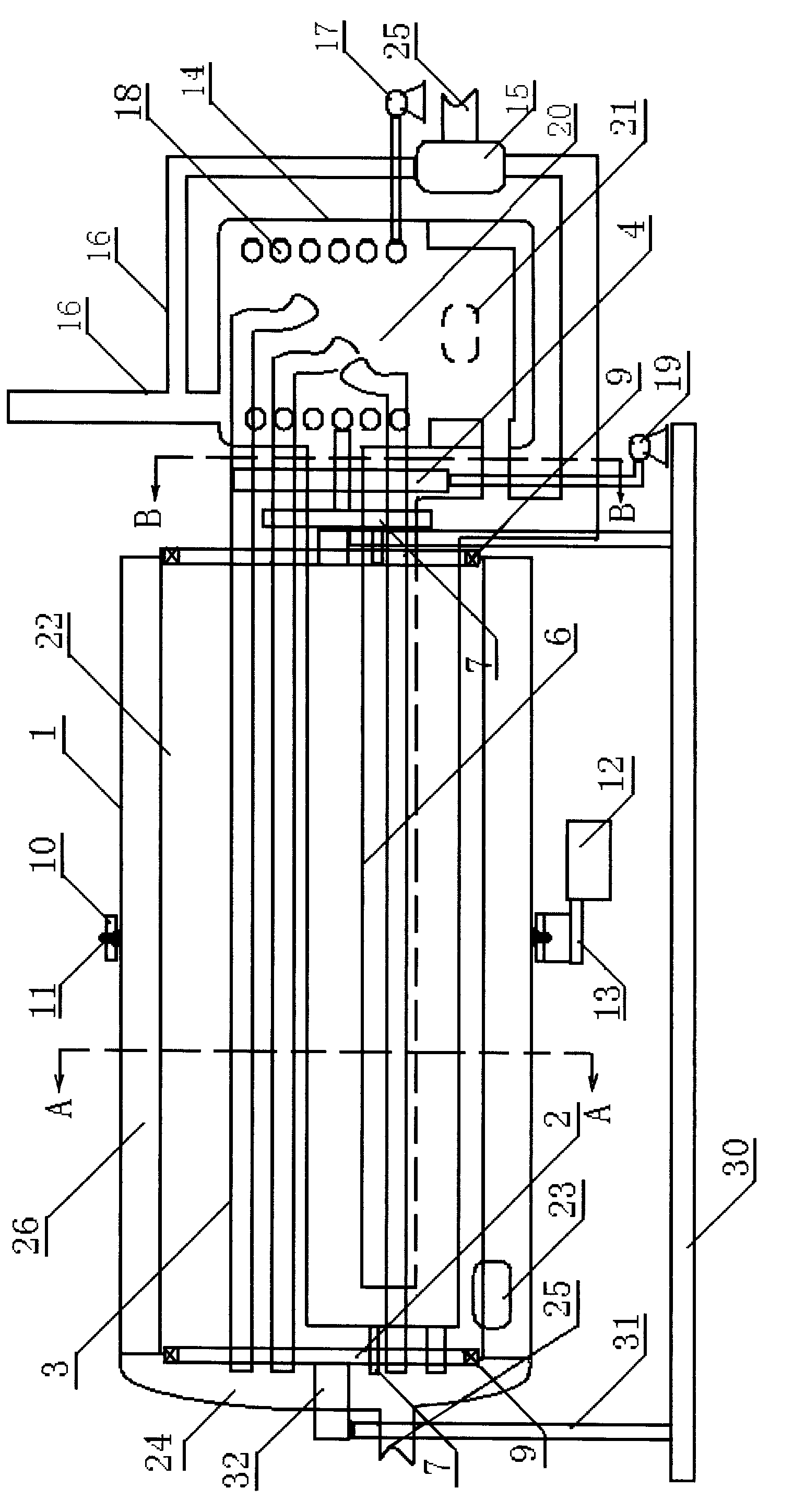
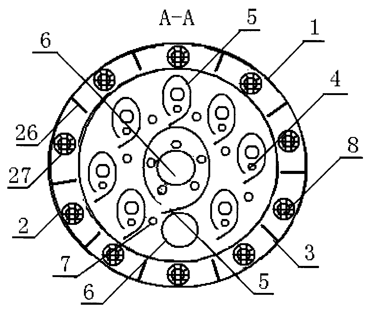
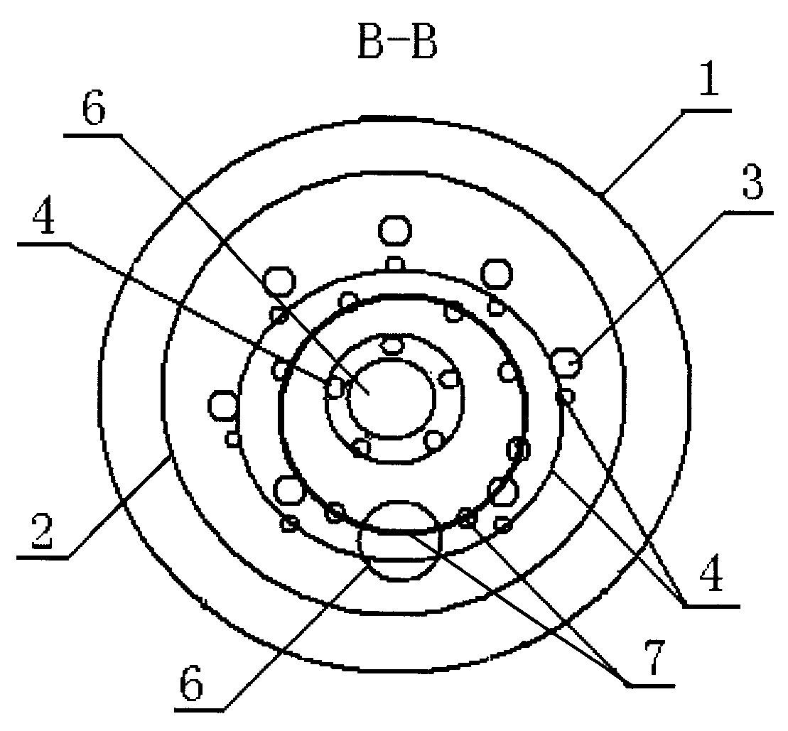
[0007] Specific implementation mode one: combine figure 1 , figure 2 , image 3 The present embodiment will be described. This embodiment consists of a drying cylinder 1, a stator shaft disk 2, a superconducting heat pipe 3, an air pipe 4, an anti-scalding cyclone cover 5, a flue 6, a hot air pipe 7, a bearing 9, a sprocket 10, a gear tooth 11, a deceleration 12, reducer output shaft 13, heating furnace 14, dust collector 15, exhaust duct 16, hot air blower 17, annular air heat pipe 18, fan 19, grain shifting plate 26 and filter screen 27, the stator shaft disk 2 is symmetrical It is arranged at both ends of the drying cylinder 1, and the end surface of the stator shaft disk 2 is provided with a bearing 9, the outer ring of the bearing 9 is connected with the drying cylinder 1, and the left ends of a plurality of superconducting heat pipes 3 are evenly arranged on the stator shaft disk at the left end 2, the right end of a plurality of superconducting heat pipes 3 is set i...

specific Embodiment approach 2

[0008] Specific implementation mode two: combination figure 1 , figure 2 , image 3 The present embodiment will be described. This embodiment also includes a base 30, a support rod 31 and a connecting shaft 32, the lower end of the supporting rod 31 is connected to the base 30, the upper end of the supporting rod 31 is connected to the connecting shaft 32, and the end of the connecting shaft 32 is connected to the stator shaft disk 2 connect. The base 30 is provided with wheels and can be moved by traction.

specific Embodiment approach 3

[0009] Specific implementation mode three: combination figure 1 The present embodiment will be described. Industrial coke is installed in the dust collector 15 of this embodiment.


PUM

PropertyMeasurementUnit
Diameteraaaaaaaaaa
Diameteraaaaaaaaaa
Diameteraaaaaaaaaa

Abstract

The invention discloses a horizontal convection integral grain drying machine, relating to a grain drying machine. By using the horizontal convection integral grain drying machine, the problems of high cost, low efficiency, low temperature, low warming speed, large energy consumption and pollutant discharge are solved. The stator reels of the grain drying machine are symmetrically arranged on two ends of a drying cylinder; a superconductive tube is arranged in the drying cylinder; the right end of the superconductive tube is arranged in the combustion chamber of a heat supply furnace by the stator reels; an air tube is arranged below the superconductive tube; the air tube and the superconductive tube are arranged in a hot-proof cyclone cover below which a hot wind port is arranged; and a dust catcher is arranged between a flue and a discharge flue. The horizontal convection integral grain drying machine has the advantages of compact design, small volume, simple structure, low cost, high efficiency and low cost, and is convenient in installation, is energy-saving, environment-friendly, wherein the grain drying machine can save energy by 30-40% and save electricity by 20-30% if compared with the existing drying equipment under the same condition, and improve efficiency by 15-20% if compared with the existing drying equipment, and the cost of the grain drying machine is 60-70% of that of the existing equipment.

Description

technical field [0001] The present invention relates to grain dryers. Specifically relates to a horizontal convection whole grain dryer. Background technique [0002] At present, my country is the world's largest grain producer and consumer, and the National Grain Bureau sample shows that due to natural cooling and poor grain storage facilities, the grain loss during storage is 150×10 higher 8 ~200×10 8 kg, the annual loss rate is 3% to 5% in the north and 5% to 8% in the south. At present, there are many types of grain dryers, mainly tower-type, with drying methods such as cross-flow, counter-current, downstream, and mixed. Pollution emission, the existing drying equipment is easy to cause grain burnt and smoke, which leads to the problem that the quality of the dried grain is reduced. Contents of the invention [0003] The present invention aims to solve the problem of backward technology of existing tower dryers, high cost, low efficiency, low temperature and slow h...

Claims


Application Information

Patent Timeline
IPC IPC(8): A23B9/08
Inventor 刘晓颖刘明礼
Owner HARBIN ZHONGSHENGLONG HEATING EQUIP TECH DEV
Learn More