Device for measuring scattering property of light diffuser and measurement method thereof

A technology of scattering characteristics and measuring device, applied in the field of lithography, can solve the problems of inaccurate measurement of the mirror image aberration of the projection object, inability to measure the mirror image difference of the projection object, etc., and achieve the effect of accurate measurement

Active Publication Date: 2011-05-25
SHANGHAI MICRO ELECTRONICS EQUIP (GRP) CO LTD
View PDF0 Cites 4 Cited by
  • Summary
  • Abstract
  • Description
  • Claims
  • Application Information

AI Technical Summary

Problems solved by technology

[0014] The scattering characteristics of the light diffuser can be measured by the scattering angle of the light diffuser, the transmittance of the light diffuser, the relationship between the scattering angle of the light diffuser and the incident angle, the improvement of the pupil non-uniformity of the lithography projection objective by the light diffuser, etc. The determination of these parameters is very important for the on-line measurement and in-situ measurement of the lithographic projection object image aberration. If these parameters cannot be determined, the projection object image aberration cannot be measured in the lithography equipment. If these parameters are determined to be inaccurate , the measurement of the projected object mirror difference in the lithography equipment is inaccurate

Method used


Image

  • Device for measuring scattering property of light diffuser and measurement method thereof
  • Device for measuring scattering property of light diffuser and measurement method thereof
  • Device for measuring scattering property of light diffuser and measurement method thereof

Examples


Embodiment 1

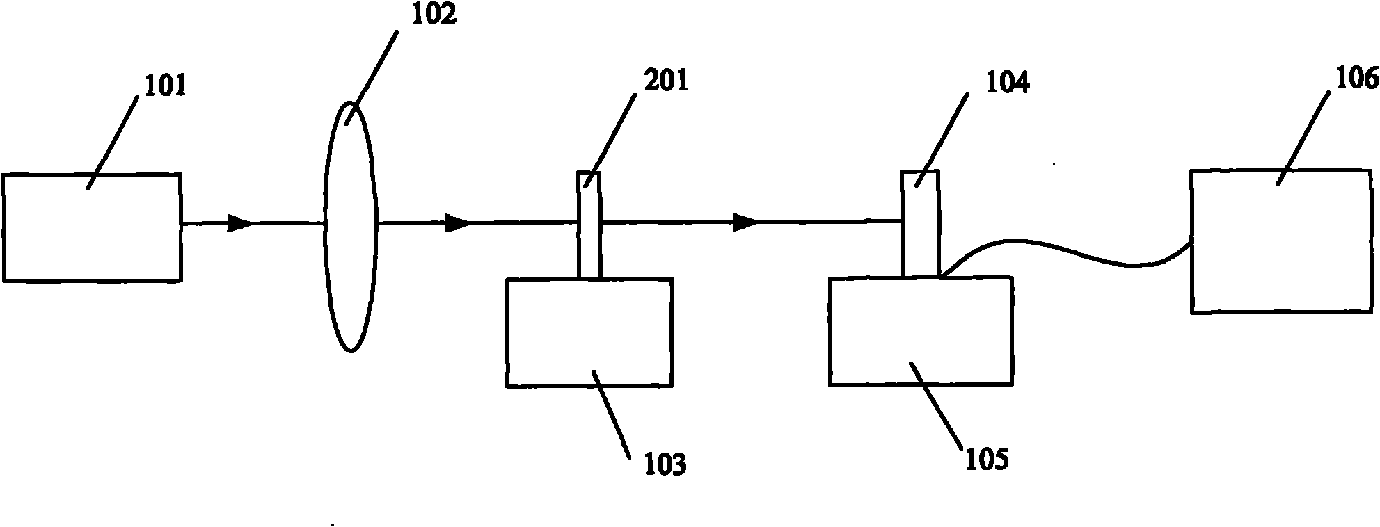
[0047] The light source 101 adopts a tunable excimer laser light source whose working gas is argon (Ar) and fluorine (F) mixed gas. The light source 101 outputs deep ultraviolet light with a wavelength of 193nm. The output spot size of the light source 101 is 6mm ×3mm, its repetition frequency can be tuned in the range of 10Hz-500Hz, and its pulse energy can be tuned in the range of 2mJ-5mJ.

[0048] For the light source 101 to output deep ultraviolet light with a wavelength of 193nm, the numerical aperture NA of the illumination objective lens 102 can be adjusted in the range of 0.17-0.05, and the field of view of the illumination objective lens 102 is 1 mm.

[0049] The minimum scale of the rotating dial of the light diffuser moving platform 103 is 1 degree.

[0050] The minimum scale of the graduated head of the detector motion platform 105 is 1 micron.

[0051] The size of the photosensitive pixel of the detector 104 is 25um×25um, and the photosensitive surface is an arra...

Embodiment 2

[0062] The light source 101 adopts a tunable excimer laser light source whose working gas is a mixture of krypton gas (Kr) and fluorine gas (F). The light source 101 outputs deep ultraviolet light with a wavelength of 248nm. The output spot size of the light source 101 is 6mm ×3mm, its repetition frequency can be tuned in the range of 10Hz-500Hz, and its pulse energy can be tuned in the range of 2mJ-5mJ.

[0063] For the light source 101 to output deep ultraviolet light with a wavelength of 248nm, the numerical aperture NA of the illumination objective lens 102 can be adjusted in the range of 0.13-0.04, and the field of view of the illumination objective lens 102 is 1mm.

[0064] The minimum scale of the rotating dial of the light diffuser moving platform 103 is 1 degree.

[0065] The minimum scale of the graduated head of the detector motion platform 105 is 1 micron.

[0066] The size of the photosensitive pixel of the detector 104 is 25um×25um, and the photosensitive surfac...


PUM

PropertyMeasurementUnit
angleaaaaaaaaaa

Abstract

The invention relates to a device for measuring the scattering property of a light diffuser and a measurement method thereof, which are used for measuring scattering property parameters of the light diffuser for on-line measurement and in-site measurement of photoetching projection objective aberration. The device for measuring the scattering property of the light diffuser comprises a light source, an illumination objective, a light diffuser motion platform, a detector, a detector motion platform and a detector reading device; the light source, the illumination objective, the light diffuser motion platform and the detector motion platform are arranged sequentially; the detector is arranged on the detector motion platform; a detected light diffuser is arranged on the light diffuser motion platform; an input end of the detector reading device is connected with an output end of the detector; and the light source, the illumination objective, the detected light diffuser and the detector are arranged along the same optical axis. Through the device for measuring the scattering property of the light diffuser and the measurement method thereof, each scattering property parameter of the light diffuser can be measured, and one measurement device has multiple measurement functions.

Description

technical field [0001] The invention relates to the technical field of photolithography, in particular to a device for measuring scattering characteristics of a light diffuser and a method thereof. Background technique [0002] Photolithography is a technology that uses a selected radiation source (such as an ultraviolet light source) to expose a specified position on a substrate (such as a silicon wafer) coated with a radiation-sensitive substance to manufacture a device. [0003] Under the trend of shrinking CD, the key dimension of semiconductor devices, improving the image resolution of the optical system in lithography equipment is the key. In lithography equipment, the optical system includes an illumination system and a lithography projection objective lens. [0004] The wavelength λ of the light source of the illumination system, the numerical aperture NA of the lithography projection objective lens and the process factor K1 are the factors that determine the resolu...

Claims


Application Information

Patent Timeline
Patent Type & Authority Applications(China)
IPC IPC(8): G01M11/02G03F7/20
Inventor 蔡燕民
Owner SHANGHAI MICRO ELECTRONICS EQUIP (GRP) CO LTD
Why Eureka
Try Eureka