Method for echo direction estimation of sensor array and for multibeam echo depth sounding and bottom detection

A sensor array and direction estimation technology, which is applied in sensor array signal processing and sonar fields, can solve the problems of poor real-time performance, small number of sampling points, limited number of samples, etc., and achieves the advantages of easy engineering application, fast calculation speed, and reduced number Effect

Inactive Publication Date: 2011-06-08
ZHEJIANG UNIV
View PDF2 Cites 9 Cited by
  • Summary
  • Abstract
  • Description
  • Claims
  • Application Information

AI Technical Summary

Problems solved by technology

[0003] When applying the high-resolution processing method in the multi-beam echo sounding system, the following aspects need to be considered: First, the received signal of the multi-beam echo sounding system is the bottom backscatter signal, which needs to meet the requirements of high-resolution processing. The algorithm has requirements for noise characteristics and signal-to-noise ratio; secondly, the transmitted signals of the multi-beam echo sounding system are usually high-frequency and narrow-band, and the number of sampling points in one echo pulse is small, and the continuous distribution of the seabed results in echo signal Non-stationarity in time limits the number of samples that can be used for high-resolution echo azimuth estimation; in addition, in order to improve resolution and coverage width, the receiving array of the system is usually a non-linear array. There is a high demand for applicability
Although the estimation performance of the MUSIC algorithm and related subspace fitting algorithms is g...

Method used


Image

  • Method for echo direction estimation of sensor array and for multibeam echo depth sounding and bottom detection
  • Method for echo direction estimation of sensor array and for multibeam echo depth sounding and bottom detection
  • Method for echo direction estimation of sensor array and for multibeam echo depth sounding and bottom detection

Examples


Embodiment Construction

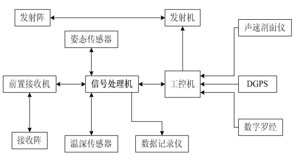
[0045] The basic concept of the present invention is to provide a high-resolution method for estimating the echo direction of sensor arrays. This method combines multi-subarray processing technology, virtual transformation technology and beam steering technology to obtain higher-precision multi-directional echoes. The orientation estimation of , while reducing the computational complexity, is beneficial to real-time applications. At the same time, this method is applied to the signal processor of the multi-beam echo sounding system, and a bottom detection method capable of distinguishing echoes from multiple directions is obtained, which realizes high spatial resolution processing of bottom echo signals. A typical composition of a multi-beam system is as follows: figure 1 shown. The main function of the signal processor is to realize the real-time acquisition and processing of the signals received by the sensor array, transmit the collected data and processing results to the ...


PUM


Abstract

The invention discloses a method for echo direction estimation of a sensor array and for multibeam echo depth sounding and bottom detection. The method for echo direction estimation of the sensor array comprises the following steps: (1) scanning beams and detecting echoes of data received by the array to obtain a space region corresponding to the echo and select more than three desired angles; (2) acquiring the output beams of each sub-array or each virtual sub-array at each desire angle and obtaining the delay relationship between every two sub-arrays or every two virtual sub-arrays; and (3) estimating the direction of each echo by utilizing a high-resolution signal arrival direction angle estimation algorithm based on the output beams and the delay relationship which are obtained in the step (2). The method disclosed in the invention is suitable for sensor arrays with irregular shapes, and can break up the restriction of the resolution by the array aperture so as to improve the bottom detection accuracy of edge beams of a multibeam echo detection system. By utilizing the method, the requirement for data while the high-resolution signal arrival direction angle estimation algorithm is conducted is lowered so as to facilitate the engineering application.

Description

technical field [0001] The invention belongs to the field of sensor array signal processing and sonar technology, and particularly relates to a high-resolution detection method for a multi-beam echo sounding system. Background technique [0002] A basic part of multi-beam echo sounding bottom detection processing is the azimuth estimation of echo signals. Usually, the multi-beam echo sounding system performs spatial filtering on the received echo signal through conventional beamforming, and then obtains the distance and direction of arrival estimation of the bottom echo through further bottom detection processing. Under the condition of a certain array aperture, the spatial resolution of conventional beamforming is limited, and the beamwidth of the actual system is usually 1.5° to 3°; for a linear array, the beamwidth of the edge deviates from the normal and transverse direction is larger, close to 6°. The underwater footprint corresponding to the beam expands with the incr...

Claims


Application Information

Patent Timeline
IPC IPC(8): G01S7/539G01S15/08G01S15/06
Inventor 姜莹徐文章惠泉
Owner ZHEJIANG UNIV
Why Eureka
Try Eureka