Delay lock loop and associated method
A technology of delay-locked loop and delay unit, applied in automatic control of power, electrical components, etc., can solve the demand of dynamic random access memory that cannot achieve high transmission data rate, data access time point or signal level error, etc. question
- Summary
- Abstract
- Description
- Claims
- Application Information
AI Technical Summary
Problems solved by technology
Method used
Image

Examples
Embodiment Construction
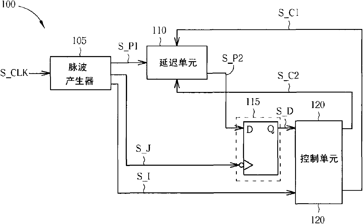
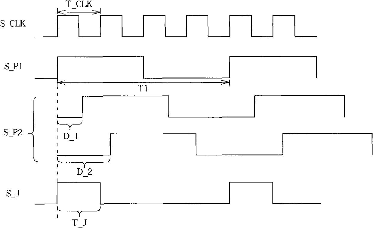
[0013] Please refer to figure 1 and figure 2 , figure 1 is a schematic diagram of the delay-locked loop 100 of the first embodiment of the present invention, figure 2 yes figure 1 A schematic diagram of signal relationships included in the delay locked loop 100 . Such as figure 1 As shown, the delay locked loop 100 includes a pulse generator 105 , a delay unit 110 , a phase detector 115 and a control unit 120 . The delay unit 110 is realized by a digital control delay line (Digital Controlled Delay Line, DCDL), and the phase detector 115 is realized by a D-type flip-flop (Flip Flop), a clock input terminal of the D-type flip-flop Used to receive a judgment signal S_J generated by the pulse generator 105, a data input end of the D-type flip-flop is used to receive a delayed pulse signal S_P2 output by the delay unit 110, and the D-type flip-flop A data output terminal is used for generating a detection result signal S_D to the control unit 120 according to the judgment ...
PUM
 Abstract
Description
Claims
Application Information
 - R&D
- Intellectual Property
- Life Sciences
- Materials
- Tech Scout
- Unparalleled Data Quality
- Higher Quality Content
- 60% Fewer Hallucinations
Browse by: Latest US Patents, China's latest patents, Technical Efficacy Thesaurus, Application Domain, Technology Topic, Popular Technical Reports.
© 2025 PatSnap. All rights reserved.Legal|Privacy policy|Modern Slavery Act Transparency Statement|Sitemap|About US| Contact US: help@patsnap.com