Separable large-section truss girder hydraulic lifting device

A hydraulic lifting, large-segment technology, used in lifting devices, erecting/assembling bridges, bridges, etc., can solve the problems of reverse structural deformation, increase equipment weight, heavy weight, etc. Steel amount, the effect of improving adaptability

Active Publication Date: 2011-06-15
SHANGHAI FOUND ENG GRP
View PDF0 Cites 21 Cited by
  • Summary
  • Abstract
  • Description
  • Claims
  • Application Information

AI Technical Summary

Problems solved by technology

[0003] Double-layer truss girder sections are large in size and heavy in weight, and the fulcrum position of the hoisting equipment is limited. It must be supported and anchored on the main truss girder; due to the wide bridge deck and large spacing between the main trusses, if the integral hoisting equipment is used, It will greatly increase the weight of the equipment; at the same time, during the entire load conversion process of the segment from hanging cables and tensioning stay cables to lifting equipment loose hooks, the structure will produce reverse deformation, which will affect the assembly of the entire bridge steel structure in the form of full welding. is unfavorable, therefore, lifting equipment must be designed to minimize its own weight
These problems have brought great difficulties to the design and selection of bridge deck segment lifting equipment

Method used


Image

  • Separable large-section truss girder hydraulic lifting device
  • Separable large-section truss girder hydraulic lifting device

Examples


Embodiment Construction

[0023] Below in conjunction with specific examples, the implementation manner of the patent of the present invention is further described. It should be understood that these examples are only used to illustrate the patented invention and are not intended to limit the scope of the patented invention. In addition, it should be understood that after reading the content taught by the patent of the present invention, those skilled in the art can make various changes or modifications to the present invention, and these equivalent forms also fall within the scope defined by the appended claims of the present application.

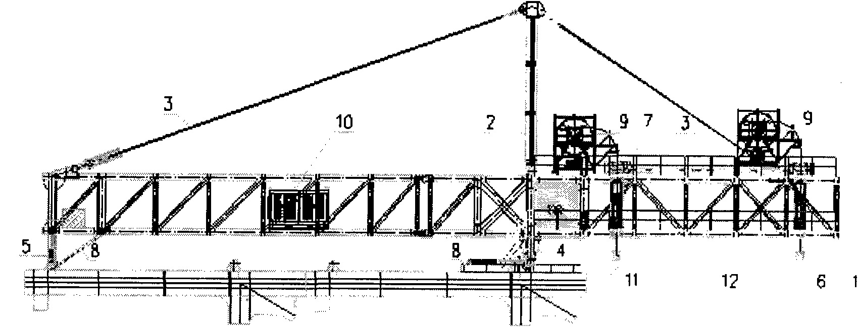
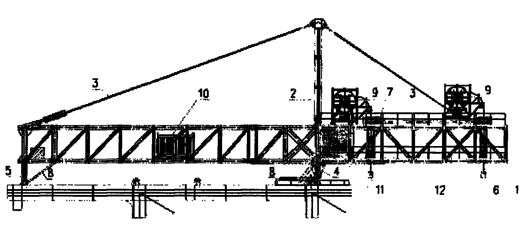
[0024] Such as figure 1 As shown, the separated large segment truss beam hydraulic lifting device of the present invention includes a main bearing truss 1; a steel tower 2; a cable system 3; a front fulcrum pad beam 4; a rear anchor point anchorage 5; Frame 6; longitudinal adjustment device 7; self-propelled system 8; cable tray and guide frame 9; hydraulic pump s...


PUM


Abstract

The invention relates to a separable large-section truss girder hydraulic lifting device. The separable large-section truss girder hydraulic lifting device comprises a main bearing structure, a positioning and anchoring system, a main lifting system, a running system, a hydraulic pump station power system, and a computer control and operation system, wherein the main bearing structure consists ofa main bearing truss, a steel tower and a pulling rope, and is a tower, rope and girder combined system; the main bearing truss is a main girder; the steel tower is in a lattice form; a steel anchor girder is arranged on the top of the steel tower; the pulling rope is anchored on the bearing truss and the steel tower respectively; the two ends of a front rope are fixed, and one end of a rear ropeis fixed and the other end of the rear rope is tensioned; and the whole main bearing structure is triangular. In the main bearing structure of the separable large-section truss girder hydraulic lifting device, the structural bearing capacity is improved by a method of pre-stressing the main bearing truss by using parallel steel ropes, so the structural gravity is reduced. By a technology of controlling hydraulic lifting by using a computer, precise control, such as synchronous lifting control, single top lifting control, longitudinal movement adjusting control and the like, can be realized under the condition of a large deviation between a front lifting load and a rear lifting load, and the precision is up to 1 millimeter.

Description

technical field [0001] The invention relates to a hoisting and lifting device for a large structure, in particular to a hydraulic lifting device for segmental beams of bridge steel truss structures. Background technique [0002] With the development of society and economy, the construction of long-span bridges presents an unprecedented scale. Among many long-span bridge types, "cable-stayed bridge" has been widely used because of its relatively mature design theory and construction technology, and the economical efficiency of the cable-stayed bridge system within a span of 1,000 meters. On the other hand, in order to make rational use of limited bridge site resources, give full play to the advantages of collinearity, and improve traffic operation capacity, more and more double-deck bridge projects will appear in the construction of long-span bridges. [0003] Double-layer truss girder sections are large in size and heavy in weight, and the fulcrum position of the hoisting e...

Claims


Application Information

Patent Timeline
Patent Type & Authority Applications(China)
IPC IPC(8): E01D21/00B66F11/00
Inventor 金东华顾海欢刘文伍小平
Owner SHANGHAI FOUND ENG GRP
Why Eureka
Try Eureka