
Gradient coil design method in nuclear magnetic resonance system

A gradient coil and nuclear magnetic resonance technology is applied in the field of superconductivity to achieve the effects of easy engineering processing, good linearity and high coil efficiency

Inactive Publication Date: 2011-06-15
SUZHOU LONWIN MEDICAL SYST
View PDF0 Cites 21 Cited by
  • Summary
  • Abstract
  • Description
  • Claims
  • Application Information

AI Technical Summary

Problems solved by technology

The initial target field method does not constrain the length of the coil. In practice, the length of the gradient coil is often constrained, and the design should be controlled according to the requirements.

Method used

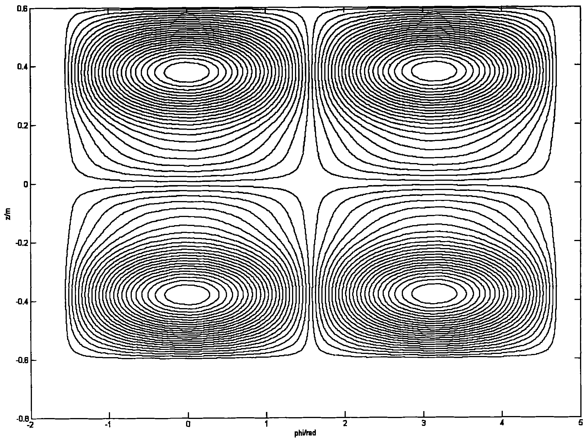
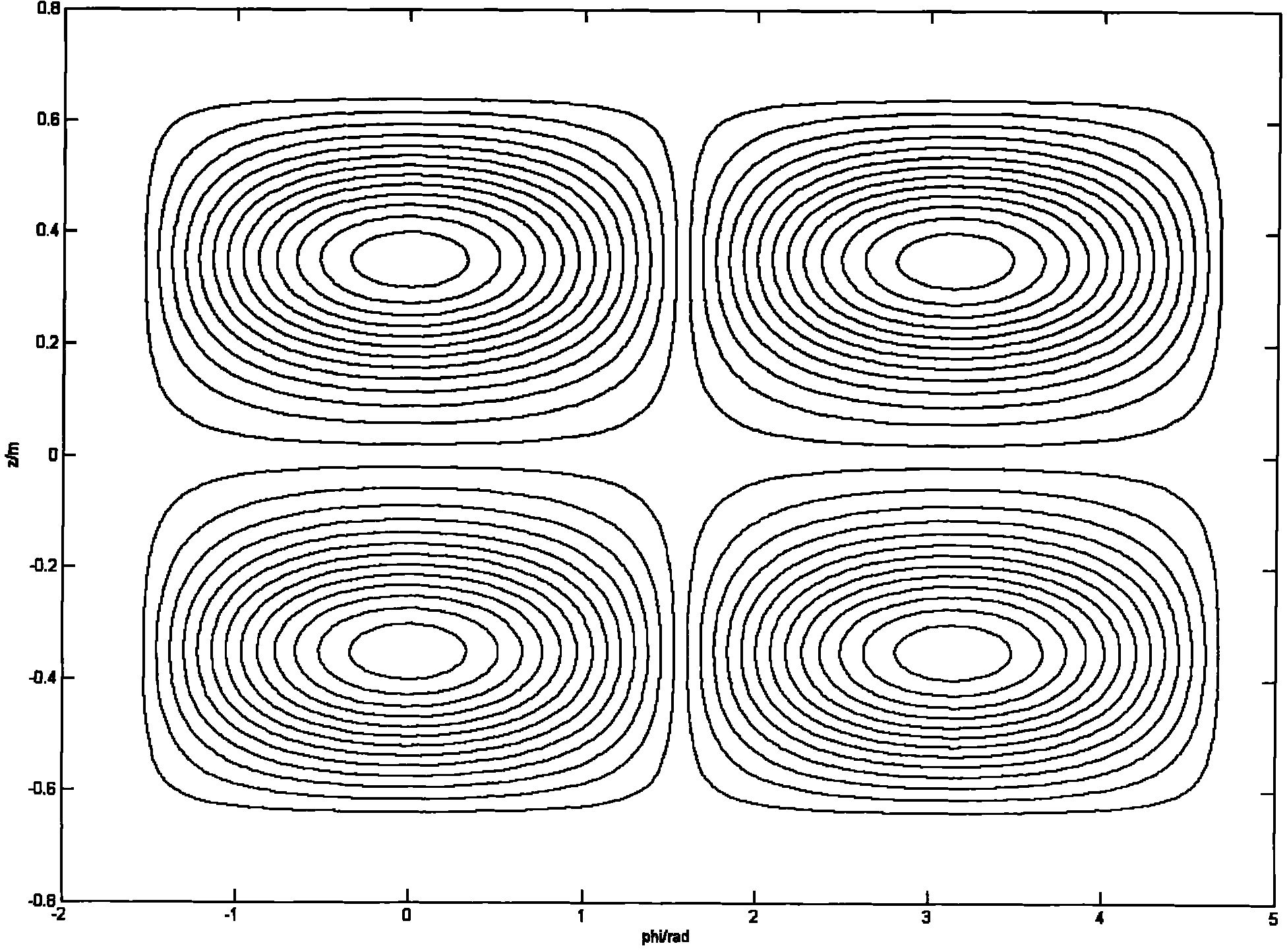
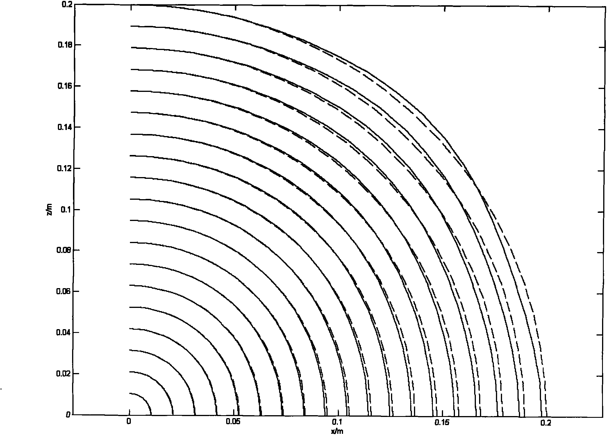

Image

  • Gradient coil design method in nuclear magnetic resonance system
  • Gradient coil design method in nuclear magnetic resonance system
  • Gradient coil design method in nuclear magnetic resonance system

Examples


Embodiment Construction

[0049]Step (1), input the preset conditions to the computer, including the radius of the main coil and the shielding coil, the wiring length, the expansion order of the current density, the expansion order of the target field and the shielding field, the disturbance range of the target field and the gradient field, and the shielding field test Dot radius, minimum wiring spacing, target gradient strength, gradient linear region diameter.

[0050] Step (2), calculating the target field coefficient matrix D inside the gradient coil, the method is as follows:

[0051] In the spherical coordinate system, define the field point Source The radius of the coil is a and the length is L. The current is distributed on a cylindrical surface with radius a, expressed as

[0052] According to Pizza's theorem:

[0053] dB = μ 0 4 π ▿ 1 | ...


PUM


Abstract

The invention discloses a gradient coil design method in a nuclear magnetic resonance system. The method comprises the following steps of: establishing a mathematical relation between a field expansion harmonic component and a cylindrical surface current distribution harmonic component under a spherical coordinate system based on a current distribution harmonic component coefficient capable of generating a specific target field through solving; combining the traditional harmonic method with a target field method; and introducing a simulated annealing algorithm to optimize and obtain the global optimum current distribution. The gradient coil design method can be used for designing a self-shielding gradient coil with cylindrical surface current distribution and optionally restraining the coil length, and ensures excellent linearity while the higher coil efficiency is achieved through comprehensively considering a plurality of design indexes. Since the gradient coil design method is optimized by utilizing a global search algorithm-simulated annealing algorithm, a global optimum design result is ensured. Meanwhile the position information of the actual distribution of a current lead is directly output by the design result, therefore, the engineering processing and manufacturing are facilitated.

Description

technical field [0001] The invention relates to the technical field of superconductivity, in particular to a gradient coil design method in a nuclear magnetic resonance system. Background technique [0002] In an MRI system, the main magnet and a series of shim coils together generate a main magnetic field B that is highly uniform along the z direction 0 . In order to provide spatial information of MR images, it is necessary to add a gradient coil to generate a pulsed linear gradient field superimposed on the main magnetic field, so that the z component of the magnetic field in the imaging space (DSV) changes linearly in the x, y, and z directions, respectively. The strength of the gradient field can be described by the following formula: [0003] G x = ∂ B z ∂ x , G y ...

Claims


Application Information

Patent Timeline
Patent Type & Authority Applications(China)
IPC IPC(8): G01R33/385
Inventor 唐昕
Owner SUZHOU LONWIN MEDICAL SYST
Learn More