
Method and device for controlling output light power and optical communication system

A technology for outputting light and power, applied in the laser field, can solve the problems of high implementation cost and difficult filter implementation, and achieve the effects of reducing implementation difficulty, increasing extinction ratio, and reducing spectral width.

Active Publication Date: 2011-06-15
HUAWEI TECH CO LTD
View PDF3 Cites 3 Cited by
  • Summary
  • Abstract
  • Description
  • Claims
  • Application Information

AI Technical Summary

Problems solved by technology

[0004] In the process of researching the existing technology, the inventor found that the existing method of controlling the output optical power requires the filter to have a strong out-of-band suppression, and also needs to pass the high-frequency blue-shift signal, which makes the realization of the filter more difficult , high cost to implement

Method used


Image

  • Method and device for controlling output light power and optical communication system
  • Method and device for controlling output light power and optical communication system
  • Method and device for controlling output light power and optical communication system

Examples


Embodiment Construction

[0030] The following will clearly and completely describe the technical solutions in the embodiments of the present invention with reference to the accompanying drawings in the embodiments of the present invention. Obviously, the described embodiments are only some, not all, embodiments of the present invention. Based on the embodiments of the present invention, all other embodiments obtained by persons of ordinary skill in the art without making creative efforts belong to the protection scope of the present invention.

[0031] Embodiments of the present invention provide a method and device for controlling output optical power and an optical communication system. In order to better understand the technical solutions of the embodiments of the present invention, the embodiments provided by the present invention will be described in detail below in conjunction with the accompanying drawings.

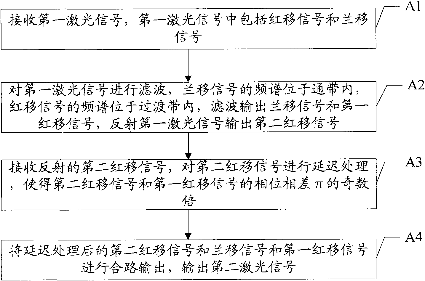
[0032] see figure 1 , figure 1 It is a flowchart of an embodiment of a method for co...


PUM


Abstract

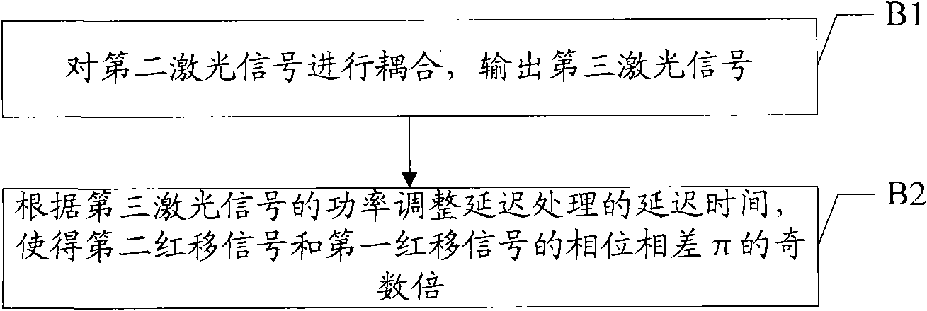
The invention discloses a method for controlling output light power, comprising the following steps: receiving a first laser signal, wherein the first laser signal comprises red shift signals and blue shift signals; filtering the first laser signal, filtering and outputting the blue shift signals and a first red shift signal, and reflecting a second red shift signal when the frequency spectrum of the blue shift signal is in a passband and the frequency spectrum of the red shift signal is in a transition zone; receiving the reflected second red shift signal, and carrying out deferred processing on the second red shift signal, so that the phase difference of the second red shift signal and the first red shift signal is odd times of pi; and combining the second red shift signal which is subjected to the deferred processing with the blue shift signals and the first red shift signal so as to output a second laser signal. According to the embodiment, the spectrum width of output signals can be decreased, the extinction ratio of the output signals is increased, the implementation difficulty of a filter can be reduced, and the implementation cost is reduced.

Description

technical field [0001] The invention relates to the field of laser technology, in particular to a method, device and optical communication system for controlling output optical power. Background technique [0002] In fiber optic communication systems, important characteristics include distortion-free transmission distance and receiver sensitivity. The difference between the sensitivity tested at the optical transmitter and the sensitivity tested at the optical receiver after optical fiber transmission is called dispersion penalty. If you need to increase the transmission distance without distortion, you can increase the output optical power of the optical transmitter, reduce the dispersion penalty, and increase the extinction ratio. When the existing directly modulated laser emits "1" and "0" bits, the carrier concentration of the laser is different, resulting in a change in the refractive index. When emitting a "1" bit, the wavelength becomes smaller and the frequency incr...

Claims


Application Information

Patent Timeline
Patent Type & Authority Applications(China)
IPC IPC(8): H04B10/08H04B10/10H04B10/17H04B10/293
Inventor 李泽彬
Owner HUAWEI TECH CO LTD
Learn More