
Internal circulation oil-cooled permanent-magnet direct-current motor

A permanent magnet direct current, oil-cooled technology, applied in the direction of electrical components, electromechanical devices, electric components, etc., can solve the problems of poor cooling effect and inability to cool permanent magnets, achieve stable work, good cooling effect, and prolong bearing life Effect

Active Publication Date: 2013-09-11
ZHEJIANG UNITE MOTOR
View PDF7 Cites 0 Cited by
  • Summary
  • Abstract
  • Description
  • Claims
  • Application Information

AI Technical Summary

Problems solved by technology

[0003] The purpose of the present invention is to provide an internal circulation oil-cooled permanent magnet DC motor, which solves the problem that the existing similar motors have poor cooling effect and cannot directly cool the permanent magnets

Method used


Image

  • Internal circulation oil-cooled permanent-magnet direct-current motor
  • Internal circulation oil-cooled permanent-magnet direct-current motor
  • Internal circulation oil-cooled permanent-magnet direct-current motor

Examples


Embodiment Construction

[0014] The present invention will be described in detail below in conjunction with the accompanying drawings and with the best embodiment.

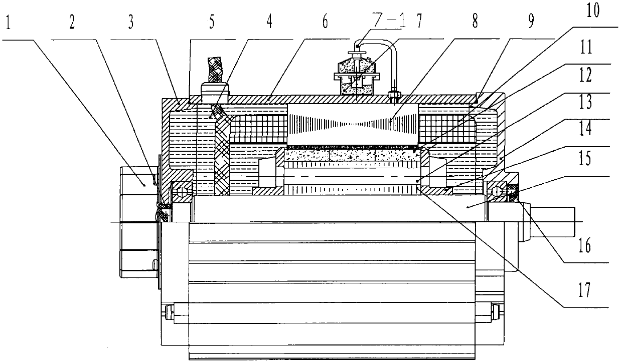
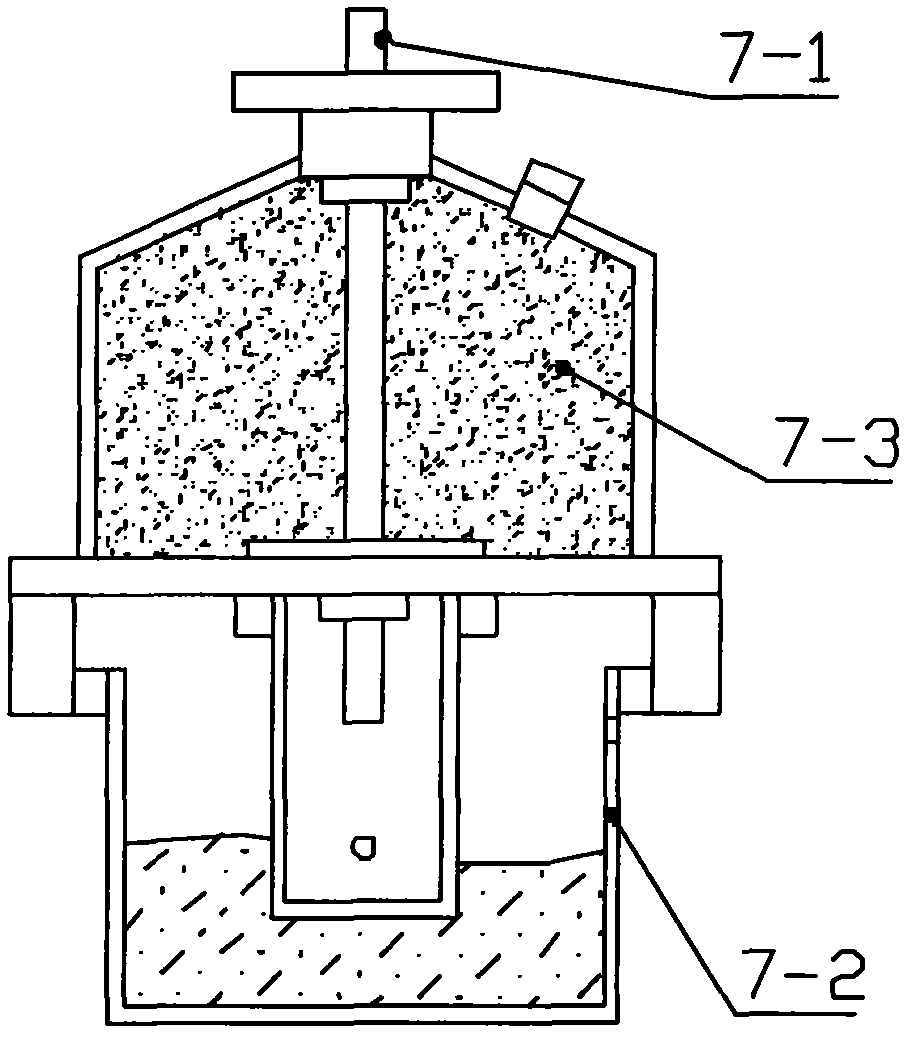
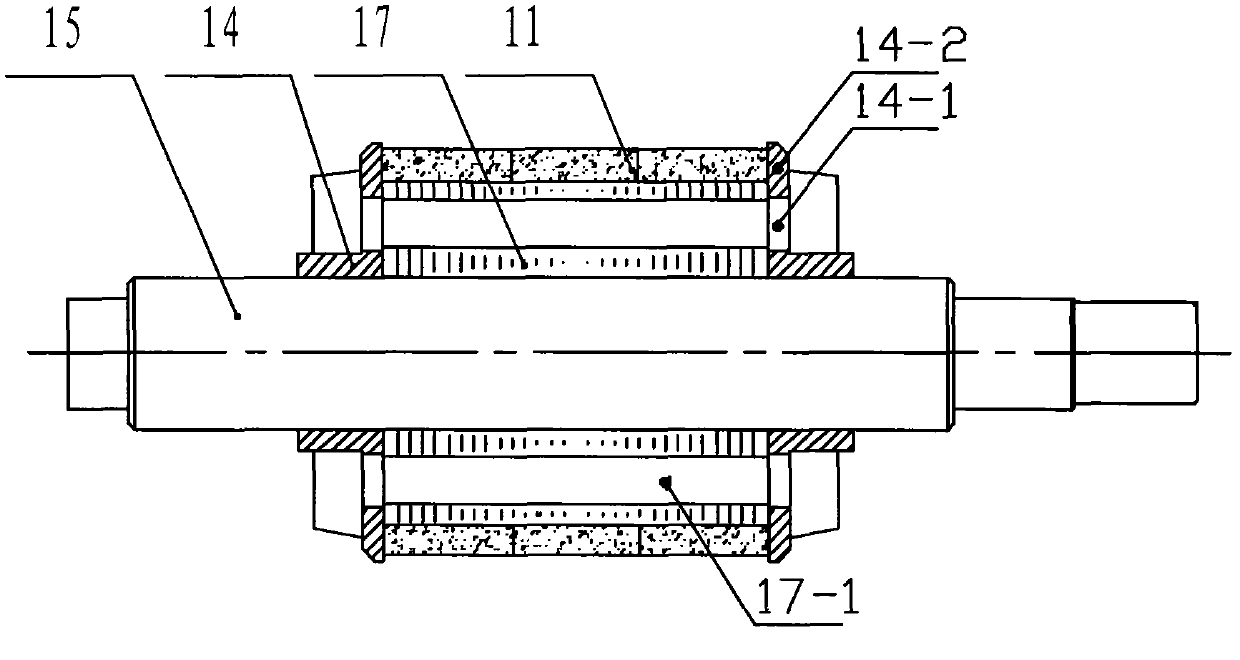
[0015] refer to Figure 1-Figure 3 , internal circulation oil-cooled permanent magnet DC motor, including rear end cover 3, housing 6, stator 8, winding coil 10, rotor 12, front end cover 13, motor shaft 15, skeleton sealing ring 16; rear end cover 3 and front end The cover 13 is respectively connected to the front and rear ends of the casing 6, the motor shaft 15 is horizontally arranged in the casing 6, the rotor 12 is installed on the motor shaft 15, the stator 8 is arranged on the outer circumference of the rotor 12, and the winding coil 10 is arranged on the stator 8; The rotor 12 is composed of disc-shaped steel sheets 17 stacked into a magnetic core, the rotor magnetic tile 11 is fixed on the periphery of the magnetic core, and the limit rings 14 are arranged at both ends of the magnetic core; it also includes a motor sealing devic...


PUM


Abstract

The invention discloses an internal circulation oil-cooled permanent-magnet direct-current motor, and relates to a permanent-magnet direct-current motor, in particular to an oil-cooled permanent-magnet direct-current brushless motor. A motor shaft is horizontally arranged in a shell; a rotor is arranged on the motor shaft; the rotor is arranged on the outer circumference of the rotor; the rotor is folded into a magnetic core by disc-shaped steel plates; a sealing device is arranged on the motor; a cooling oil circulating system is arranged in the motor; in the system, the motor is filled with cooling oil; the disc-shaped steel plates are provided with steel plate through holes; when the disc-shaped steel plates are folded into the magnetic core, cooling oil circulation channels are formed among the steel plate through holes correspondingly; limit ring blades are arranged inside two limit rings; limit ring circular holes are reserved on the limit ring blades; the positions and the number of the limit ring circular holes are consistent with the positions and the number of the steel plate through holes on the disc-shaped steel plates; a respirator is arranged out of the shell; and the two ends of a conduit of the respirator are respectively connected with the lower cavity of the shell and the inside of the shell. The internal circulation oil-cooled permanent-magnet direct-current motor solves the problems that a cooling effect is poor and a permanent-magnet cannot be cooled directly in conventional similar motors.

Description

technical field [0001] The invention relates to a permanent magnet DC motor, in particular to an oil-cooled permanent magnet DC brushless motor. Background technique [0002] The temperature of the motor directly determines the performance index of the whole machine. If the temperature is too high, it will affect the operating life and efficiency of the motor. No matter what kind of motor, the temperature index and how to dissipate heat must be considered in the motor design process. Especially for high-power motors, the improvement of heat dissipation capacity can increase the power density and torque density of the motor, while saving consumables and reducing production costs, which is conducive to the performance of the motor. At present, there are many permanent magnet brushless DC motors with various cooling structures, most of which are cooled by circulating water, and a cooling circulating water tank is set in the housing, and most of them adopt casting structure or ...

Claims


Application Information

Patent Timeline
Patent Type & Authority Patents(China)
IPC IPC(8): H02K9/197H02K5/18
Inventor 李金东
Owner ZHEJIANG UNITE MOTOR
Learn More