
Aeration biological filter chamber facility

A biological aerated filter and filter technology, applied in aerobic and anaerobic process treatment and other directions, can solve the problems of unstable removal of organic matter, nitrogen and phosphorus removal, unreasonable flushing method, and reduced biofilm activity, etc. Achieve the effect of small footprint, wide application range and less residual sludge

Active Publication Date: 2011-06-29
CHONGQING UNIV
View PDF1 Cites 24 Cited by
  • Summary
  • Abstract
  • Description
  • Claims
  • Application Information

AI Technical Summary

Problems solved by technology

It is especially suitable for sewage treatment in small towns with tight land use and backward economic development level, but the BAF structure is relatively complicated, and it is troublesome to use reinforced concrete materials for construction on a small scale, and the unit cost is relatively high
At present, there are few types of BAF filter equipment in the market, and the price is too expensive to optimize the design for the water quality and water volume characteristics of small town sewage. During use, it is easy to have low oxygenation efficiency and blockage of oxygenation equipment, and unreasonable flushing methods lead to biofilm. Reduced activity, unstable removal of organic matter and denitrification and dephosphorization effects, etc. These problems lead to the failure of large-scale application of BAF in small towns

Method used


Image

  • Aeration biological filter chamber facility
  • Aeration biological filter chamber facility
  • Aeration biological filter chamber facility

Examples


Embodiment Construction

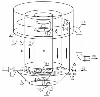
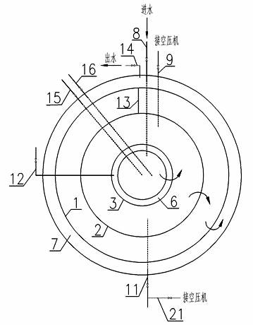
[0014] Refer to attached figure 1 and figure 2 , the equipment adopts a cylindrical stainless steel pool, the circular pool is isotropic, the stress conditions and hydraulic conditions are very good, and it occupies a small area. Under the condition of the same volume, it saves the most materials, and there are only two pools Welding seam, the probability of equipment problems is lower than that of conventional square pools.

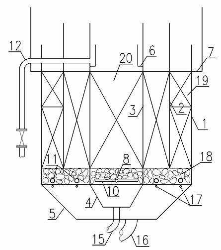
[0015] The interior of the equipment is divided into three filters from the inside to the outside by two concentric cylinders, which are the anoxic zone filter 3, the first aerobic zone filter 2 and the second aerobic zone filter 1. Each zone filter is filled with enzymatic biological filler 20 with corresponding particle size distribution. Among them, the anoxic zone filter 3 mainly plays the role of intercepting suspended solids in wastewater and hydrolytic acidification, the first aerobic zone filter 2 mainly plays the role of oxidizing and decompo...


PUM


Abstract

The invention relates to an aeration biological filter chamber facility which is an integrated sewage treatment facility in a multistage series combination technique. The aeration biological filter chamber facility comprises a chamber body, a filler layer, a supporting layer, a sludge hopper, a water inlet / outlet system, a back-purge system, various control valves and metering devices. From inside to outside, the whole facility is sequentially divided into an anaerobic zone filter chamber, a first aerobic zone filter chamber and a second aerobic zone filter chamber in the form of concentric circles. When the facility operates, sewage enters from the bottom of the inner layer anaerobic zone, sequentially flows through the filter chambers in an upflow-downflow-upflow mode, and finally converges in a water collection tank on the chamber top to be discharged. While the sewage enters, air is introduced into a microporous aeration hose on the lower part of the aerobic chamber so as to provide required oxygen for decomposing organic substances. In the back-purge stage, back-purge gas and water of the aerobic zone filter chamber share one set of perforated pipes, and a gas-water-gas three-step purge mode is adopted; and at the anaerobic zone filter chamber, a water inlet perforated pipe is utilized to carry out back-purge, and only water is used for the back-purge in the whole process. After the upflow water purge finishes, the downflow water starts purging to remove aged biomembranes, thereby ensuring the stable operation of the filter chamber.

Description

technical field [0001] The invention relates to sewage treatment equipment, in particular to a small integrated sewage treatment equipment for secondary treatment of domestic sewage and reuse of gray water. It is especially suitable for places where the water volume is relatively small, the incoming water is dispersed, the collection is difficult, and local treatment is required to meet the discharge standards, such as small towns, independent living quarters, remote military garrisons, etc., and it is especially suitable for the treatment of domestic sewage in small towns. Background technique [0002] Biological aerated filter, referred to as BAF, is a new type of biofilm sewage treatment process developed in Europe and the United States in the late 1980s. It was greatly developed in the early 1990s. This process has the ability to remove SS, COD, BOD, nitrification, denitrification and phosphorus removal. The biological aerated filter integrates biological oxidation and ...

Claims


Application Information

Patent Timeline
Patent Type & Authority Applications(China)
IPC IPC(8): C02F3/30
Inventor 何强梁建军翟俊柴宏祥陈雁玲刘明祥
Owner CHONGQING UNIV
Learn More