
Method for perceiving star catalogue topography by laser stripe information

A technology of laser stripes and information perception, applied in the direction of using optical devices, measuring devices, instruments, etc., can solve the problem of small amount of information

Active Publication Date: 2012-08-08
BEIJING INST OF CONTROL ENG
View PDF0 Cites 0 Cited by
  • Summary
  • Abstract
  • Description
  • Claims
  • Application Information

AI Technical Summary

Problems solved by technology

According to foreign relevant data, the laser streak meter is used for star surface environment perception based on structured light because of its strong initiative and high reliability, but the amount of information obtained is relatively small, and more ways to obtain and rationally use this information are listed in foreign materials and documents Much does not involve

Method used


Image

  • Method for perceiving star catalogue topography by laser stripe information
  • Method for perceiving star catalogue topography by laser stripe information
  • Method for perceiving star catalogue topography by laser stripe information

Examples


Embodiment 1

[0057] 1) Define the target object

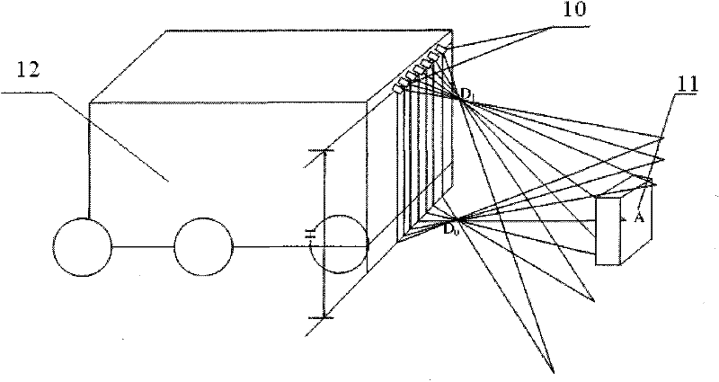
[0058] This method abstracts the star catalog detection robot in the form of a wheeled probe vehicle, and a laser streak device capable of emitting a group of inline lasers is installed at a specific position in front of the probe vehicle. It abstracts that the main hazard of walking on unstructured terrain is the raised height obstacle, which is marked as A.

[0059] The present invention will be further described in detail below in conjunction with the drawings and specific embodiments.

[0060] 2) Place a laser streak meter in front of the rover 12 to emit laser;

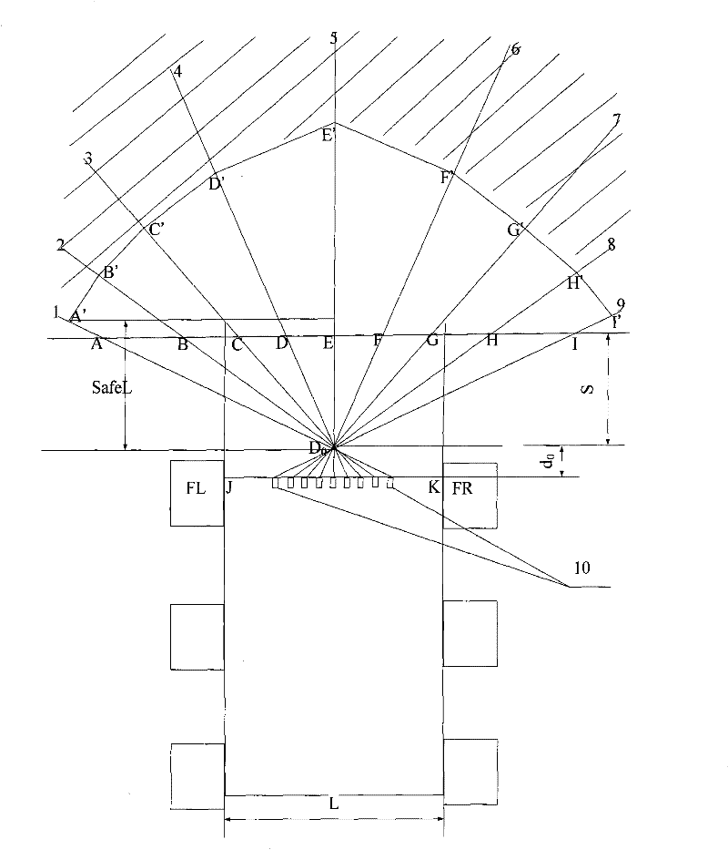
[0061] The laser streak device of the present invention is composed of a plurality of lasers 10 capable of emitting one-line laser. The laser line emitted by each laser 10 is located on a light-emitting plane 1-9. The common light-emitting planes 1-9 are The intersection is called the exit ray.

[0062] The status of the laser streak in the rover 12 is as figure 1 As shown, the laser ...

Embodiment 2

[0120] Steps 1) to 3) are the same as in Example 1.

[0121] 4) Obtain and save laser fringe information

[0122] In this embodiment, a laser streak instrument is used to assist binocular vision by using the method of intersecting the lines of optics to obtain laser streak information. The specific operation steps are as follows:

[0123] a) Make the laser stripes in the common field of view of the two cameras;

[0124] b) Turn on and turn off the two images taken by the laser streak instrument to make difference and binarization to obtain two binary images containing only laser stripes;

[0125] c) Where a point on the left image is on the epipolar line of the right image, and at the same time this point is on the laser line of the right image, the intersection of the epipolar line of the right image and the laser line is the point with the same name of the laser point on the left image.

[0126] Using different installation positions and angles, ensure that several laser stripes are lo...


PUM


Abstract

The invention belongs to the field of visual environment perception for a robot, and particularly discloses a method for perceiving star catalogue topography by laser stripe information. In the method, the topography is designed into three regions so as to evaluate perception results in advance; the defect of complex algorithm in lattice-fitting scene description is eliminated; and the provided results and design weights for the subsequent algorithm are applicable to various path planning algorithms. Compared with the traditional binocular stereo vision technology, the invention has the advantages that the speed is higher; an image pair (1024*1024) is matched with the traditional gray scale; a search window is set into the size of 5*5 and adopts an SAD (sum of absolute differences) matching mode; and the matching recovery runs once on an industrial personal computer (IPC) with a main frequency (p42.4) within about 2 minutes. By utilizing the method, points obtained through calculationare reduced, but the reliability is enhanced and the operation time is less than 1 second.

Description

Technical field [0001] The invention belongs to the field of robot visual environment perception, and specifically relates to a method for sensing the terrain of a star catalog. Background technique [0002] Using structured light to perceive the topography of the star surface has achieved certain applications in foreign planetary exploration vehicles. However, due to its relatively large power consumption, the use of binocular stereo vision in the later process of Mars exploration in the United States replaced its application in planetary surface perception. . According to foreign related materials, the structured light-based star catalog environment perception uses laser streaks because of its strong initiative and high reliability, but the amount of information obtained is small, and more methods to obtain and rationally use this information are in foreign literature. Not involved Summary of the invention [0003] The purpose of the present invention is to provide a method fo...

Claims


Application Information

Patent Timeline
Patent Type & Authority Patents(China)
IPC IPC(8): G01B11/25G01C7/02
Inventor 张晋王磊陈建新张志杨洁余志鸿曹荣向
Owner BEIJING INST OF CONTROL ENG
Learn More