Large-irradiation-area atomic oxygen beam simulation system

A simulation system, atomic oxygen technology, applied in the field of simulation system, can solve the problems of inability to carry out test verification, low test efficiency, restricting the application of test technology, etc., to shorten the test period, reduce the test cost, and improve the test efficiency.

Inactive Publication Date: 2011-07-06
BEIJING INST OF SPACECRAFT ENVIRONMENT ENG
View PDF0 Cites 6 Cited by
  • Summary
  • Abstract
  • Description
  • Claims
  • Application Information

AI Technical Summary

Problems solved by technology

The atomic oxygen equipment requires the sample size to be greater than Φ10mm, and samples of Φ25.4mm or 20mm×20mm are generally used in the test. In this case, the test efficiency of the above-mentioned equipment is low, which greatly restricts the application of test technology in engineering
In addition, due to the limitation of the irradiated area, some objects that need to be tested at the component level, such as solar cell arrays, cannot be tested and verified, which brings certain risks to the reliability design of the spacecraft.

Method used


Image

  • Large-irradiation-area atomic oxygen beam simulation system
  • Large-irradiation-area atomic oxygen beam simulation system

Examples


Embodiment 1

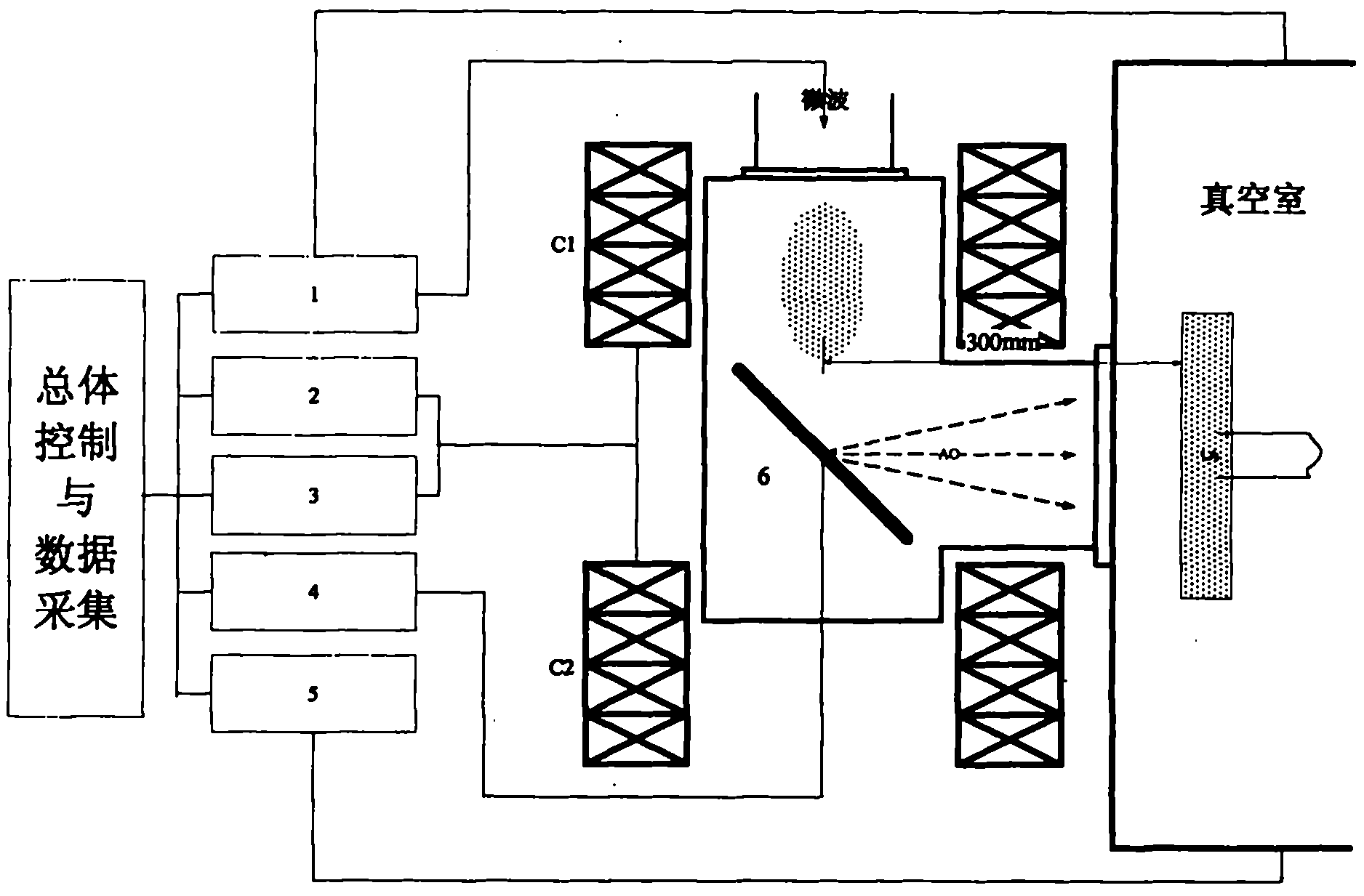
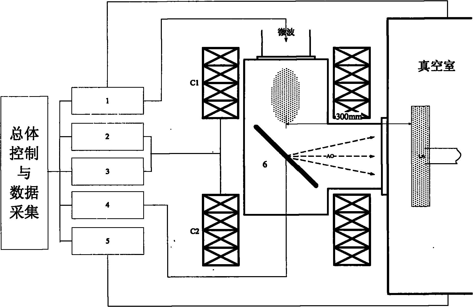
[0024] Using this large-irradiation area atomic oxygen beam simulation system, install and debug on a Φ500mm×600mm vacuum vessel to construct an atomic oxygen environment ground simulation test equipment. The atomic oxygen beam simulation system is connected with the main container through a Φ150mm flange.

[0025] According to the above methods and steps, a large irradiated area atomic oxygen beam simulation system is built. The vacuum chamber of the device is welded by non-magnetic stainless steel plates with a thickness of 4 to 5 mm, which can withstand the internal and external pressure difference caused by high vacuum and can Avoid the influence of anti-electric cavity magnetization on plasma anti-electricity. A microwave antenna window, an observation window, a molybdenum plate installation window, a molybdenum plate azimuth adjustment window, a connection window with the main container, and an electrostatic probe window are designed and processed on the container. The micr...


PUM

PropertyMeasurementUnit
thicknessaaaaaaaaaa

Abstract

The invention discloses a large-irradiation-area atomic oxygen beam simulation system. The system comprises a water-cooled electromagnetic field system, a microwave generation and transmission system, a molybdenum neutralization plate, a water cooling system, a vacuum system and a target base mechanism, wherein the water-cooled electromagnetic field system can generate a strong magnetic mirror field which can reach 1,200 gausses; the frequency of the microwave generation and transmission system is 2.45GHz and the power of the microwave generation and transmission system can reach 1,000W; the microwave generation and transmission system can excite working oxygen to ionize in the strong magnetic mirror field to generate and restrain high-density oxygen plasma; major axis length and minor axis length of the molybdenum neutralization plate are 200mm and 140mm respectively; the molybdenum neutralization plate is used for accelerating, collecting and reflecting positive ions in the plasma to form a directional atomic oxygen beam of which the sectional area diameter is more than 150mm; the water cooling system can guarantee that an atomic oxygen source can uninterruptedly and stably workfor 100 hours; the vacuum system is used for guaranteeing a vacuum condition for normal work of atomic oxygen; and the target table mechanism is used for placing a test sample in an atomic oxygen beam region. The system guarantees that a device can continuously and stably run in a high atomic oxygen beam state through measures in aspects of cooling, sealing, material selection and the like. By using the system, the atomic oxygen environmental adaptation testing efficiency of an aerospace material can be greatly improved, the test period is shortened, the test cost is reduced, the technical bottleneck of component-level atomic oxygen test can be broken through, and a simulation means is provided for more effectively verifying reliability of spacecraft design.

Description

Technical field [0001] The invention belongs to the field of space technology simulation environment, and in particular relates to a simulation system that simulates a space atomic oxygen beam on the ground and has a larger beam cross-sectional area. Background technique [0002] The atomic oxygen environment refers to the residual gas environment with atomic oxygen in the low earth orbit (generally considered to be 200-700km altitude). Space flight tests and ground simulation tests show that atomic oxygen will cause the erosion and aging of spacecraft structural materials and the decline of functional materials, which are mainly manifested in the loss of material quality and thickness, changes in surface morphology, and decline in various performance parameters. every aspect. The ground simulation test is currently the main test verification method for my country's spacecraft space atomic oxygen environment adaptability design. [0003] With the development of my country's aeros...

Claims


Application Information

Patent Timeline
Patent Type & Authority Applications(China)
IPC IPC(8): G01N17/00
Inventor 李涛姜利祥郭亮冯伟泉刘向鹏姜海富秦玮
Owner BEIJING INST OF SPACECRAFT ENVIRONMENT ENG
Why Eureka
Try Eureka