Microwave power distributor

A technology of microwave power and splitter, which is applied in the direction of waveguide devices, electrical components, connecting devices, etc., can solve the problems of limited application range, large volume, and large loss, and achieve low insertion loss, high synthesis efficiency, and simple processing Effect

Inactive Publication Date: 2011-07-13
SICHUAN LONGRUI MICROELECTRONICS
View PDF2 Cites 8 Cited by
  • Summary
  • Abstract
  • Description
  • Claims
  • Application Information

AI Technical Summary

Problems solved by technology

The power divider/combiner of the planar circuit has the advantages of small size and low cost, but the loss is relatively large; the power combiner based on the waveguide is characterized by extremely small loss

Method used


Image

  • Microwave power distributor
  • Microwave power distributor
  • Microwave power distributor

Examples


Embodiment 1

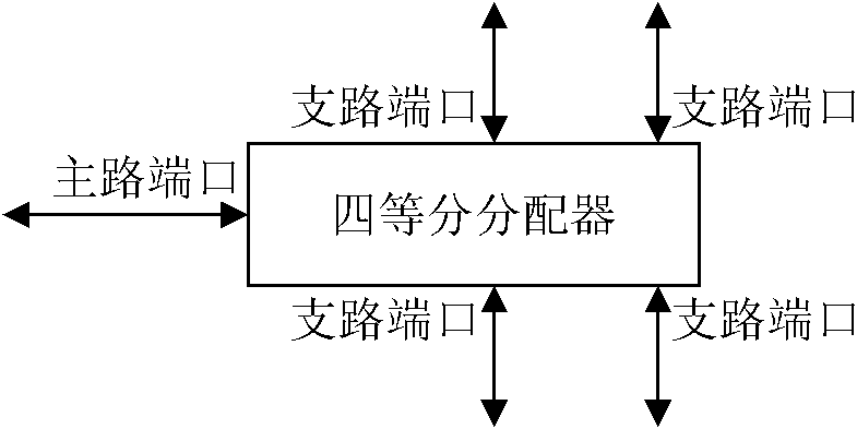
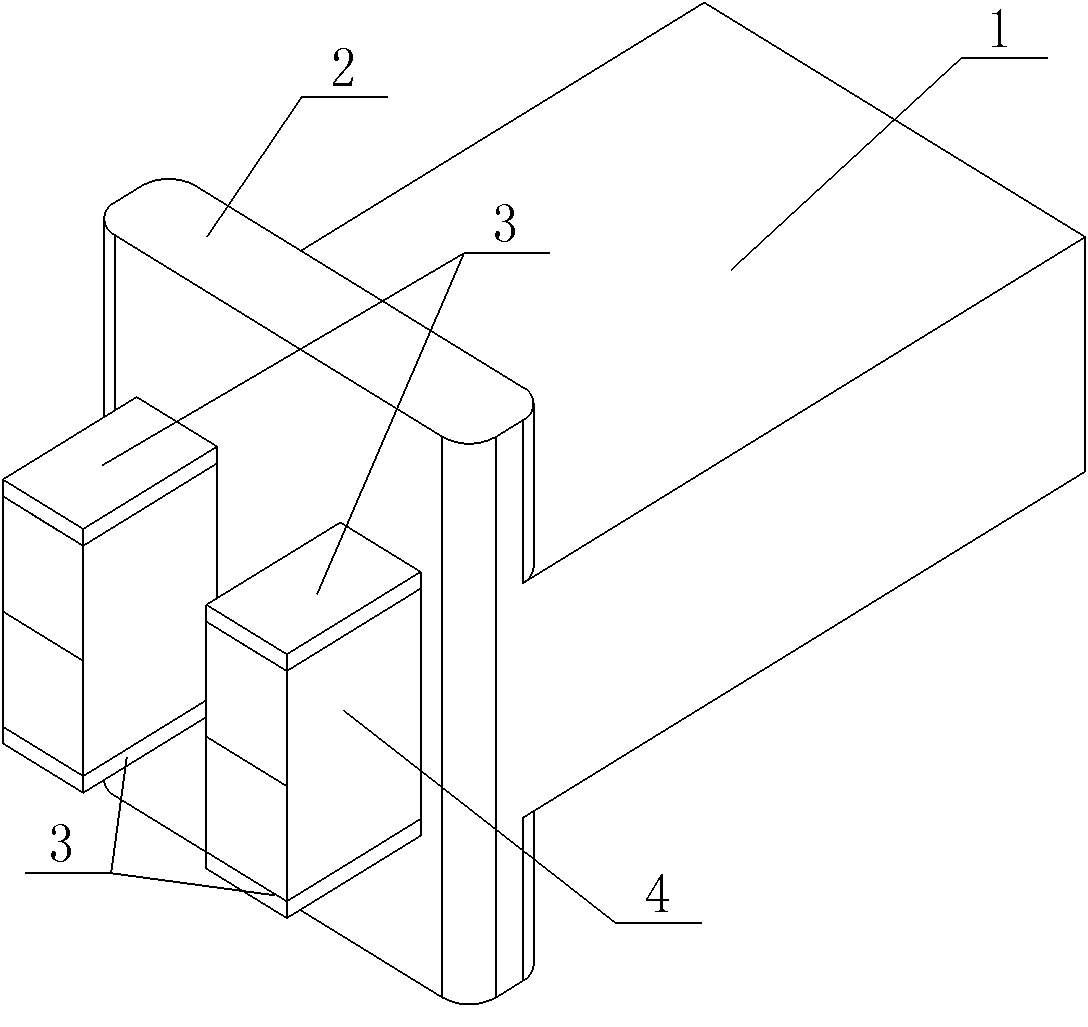
[0029] see Figure 3 ~ Figure 6 , the microwave power divider in this example is a quarter divider. Its cavity structure includes a rectangular waveguide cavity 1 and a coupling cavity 2. The coupling cavity 2 is a regular square prism, and its four edges have been chamfered to become smoother. , but keep the basic shape of the regular quadrangular prism, see image 3 and Figure 5 . The central part of one cylindrical surface of the coupling cavity 2 connects with the rectangular waveguide cavity 1 at the terminal short-circuit surface of the rectangular waveguide cavity 1 to form a whole, and the rectangular waveguide cavity 1 and the coupling cavity 2 are completely communicated. There are 4 windows on the cylinder opposite to the cylinder of the coupling cavity 2, and a coupler 3 is inserted in each window for coupling microwave signals. The microwave power divider in this example has a plane symmetrical structure, and its two orthogonal symmetrical planes ( Figure 4 ...

Embodiment 2

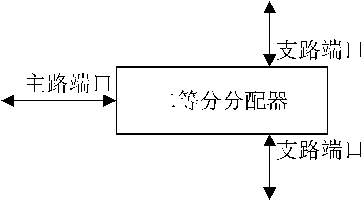
[0033] In this example, the number of microwave power splitter windows is 2, and of course there are also 2 couplers, such as Figure 10shown. This is a bisecting divider with a plane-symmetric structure, and its symmetry plane is perpendicular to the short-circuit surface of the waveguide cavity terminal. The microwave power divider in this example is divided into two parts, each of which has a window. Figure 10 The two couplers in the middle are arranged vertically, the microstrip line on the ceramic substrate of the upper coupler is downward, and the microstrip line on the ceramic substrate of the lower coupler is upward. Obviously, Figure 10 The two couplers in the middle can also adopt a lateral configuration structure, and the microstrip lines on the ceramic substrate of the coupler are arranged opposite to each other.


PUM


Abstract

The invention relates to a microwave device and discloses a microwave power distributor which is based on a waveguide technology and has a cavity structure. The technical scheme is that: the microwave power distributor comprises a rectangular waveguide cavity and a coupling cavity; the coupling cavity basically has a shape of regular quadrangular prism; the center part of one side cylindrical surface of the coupling cavity is connected and communicated with the rectangular waveguide cavity on the short circuit surface of the rectangular waveguide cavity; an even number of windows are formed on the cylindrical surface opposite to the cylindrical surface; a coupler is inserted into each window so as to couple microwave signals; the bottom surface of the regular quadrangular prism is as long as the rectangular waveguide cavity, and the height of the regular quadrangular prism is greater than the width of the rectangular waveguide cavity; the rectangular waveguide cavity is a main circuit port of the microwave power distributor; the couplers are branch circuit ports of the microwave power distributor; and all the branch circuit ports are equant ports. The microwave power distributor is used for synthesizing or distributing microwave power so as to obtain good input/output standing waves and broadband characteristics; and the microwave power distributor is easy to process and convenient to assemble.

Description

technical field [0001] The present invention relates to microwave devices, in particular to microwave power dividers or combiners. Background technique [0002] In the microwave field, the microwave power amplifier is an important device in the system composition. The most important indicators of microwave power amplifiers are output power, efficiency and gain. In recent years, solid-state microwave power devices have developed rapidly, gradually replacing the bulky traveling wave tube amplifiers in the past. Semiconductor solid-state microwave devices have the characteristics of small size, light weight, and high stability. However, the biggest disadvantage of solid-state microwave devices is their relatively low output power. In order to obtain high-power microwaves, it is often necessary to use microwave power distribution and synthesis technology, which is commonly used power dividers and synthesizers. [0003] Power splitter is also called power divider, which is divi...

Claims


Application Information

Patent Timeline
IPC IPC(8): H01P5/12
Inventor 吴旦昱陈晓娟李滨刘新宇
Owner SICHUAN LONGRUI MICROELECTRONICS
Why Eureka
Try Eureka